Install Fiber Optic Cable Pass-Thru Kit for SCC1 (Single-Carrier) Cabinets
Administering PNC Duplication
212
SI Installation and Upgrades
June 2004
Administering PNC Duplication
Return to Task List
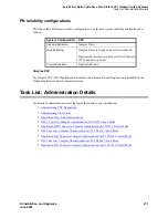
The license file enables PNC Duplication. If PNC Duplication is enabled on the System-Parameters
Customer-Options form, the following administration forms change:
•
Cabinet form
—
Additional fields appear to allow administration of switch nodes to A-PNC and
B-PNC sides of the CSS. The B-PNC is the duplicated hardware for the A-PNC. Either the A-
PNC or the B-PNC can provide full customized service. B-PNC cannot be used in a simplex PNC
configuration. Pairing of switch nodes is also defined here.
•
Fiber Link form
—
Additional fields appear to allow administration of fiber links on the B-PNC
side of the CSS. If an endpoint on the A-PNC side is administered as an SNI, its corresponding
endpoint on the B-PNC side is determined (if switch nodes are paired in the cabinet form prior to
this administration) and displayed. However, administration of the duplicate B-PNC link is not
enforced until duplication is in full operation.
•
Duplication-Related System-Parameters form
—
An additional field appears to enable operation
of PNC duplication.
Return to Task List
Administering Fiber Links
Return to Task List
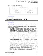
Additional fields appear on the
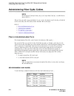
Figure 39, Fiber Link Administration form,
on page 213 to allow
administration of fiber links on the B-PNC side of the CSS. If an endpoint on the A-PNC side is
administered as an SNI, its corresponding endpoint on the B-PNC side is determined (if switch nodes are
paired in the cabinet form prior to this administration) and displayed. However, administration of the
duplicate B-PNC link is not enforced until duplication is in full operation.
The following fields appear for basic fiber link administration:
•
Fiber Link #
—
Display-only field. From the command line, enter a 1- to 3-digit number to
uniquely identify a switch connection in the system and its duplicate if appropriate.
•
Board Location
—
Enter the cabinet, carrier, and slot that identifies the physical location of an
SNI or EI board that is the first endpoint of the fiber link.
•
Board Type
—
Display-only field showing the type of circuit pack in Endpoint-1.
•
Board Location
—
Enter the cabinet, carrier, and slot that identifies the physical location of an
SNI or EI board that is the second endpoint of the fiber link.
•
Board Type
—
Display-only field showing the type of circuit pack in Endpoint-2.
•
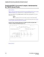
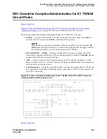
Is one endpoint remoted via a DS1 Converter Complex?
—
Enter y to specify that a DS1
Converter complex is used to remote one endpoint. If a y is entered, A-PNC DS1 Converter
circuit pack Location must be administered on Page 1. A-PNC DS1 Converter circuit pack Type
displays. A-PNC DS1 Converter (DS1CONV) Attributes must be administered on Page 2 of this
form.


