Install and Wire Telephones
Auxiliary Connector Outputs
510
SI Installation and Upgrades
June 2004
Return to Task List
Auxiliary Connector Outputs
Return to Task List
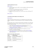
Connect a 25-pair cable from the AUX connector on the back of the control carrier to a connecting block
on the trunk/auxiliary field.
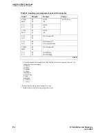
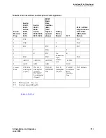
Table 21, Auxiliary Lead Appearances at AUX Connector,
on page 511 shows the Control Carrier outputs
cable pinouts. The Control Carrier AUX connector outputs include:
•
Alarm monitoring for the auxiliary cabinet
•
Seven -48 VDC power sources for emergency transfer units
•
Three -48 VDC power sources for remotely powering three attendant consoles or telephone
adjuncts
•
The remote management terminal interface trunk connection location
•
A relay contact that actuates a customer-supplied light, bell, or similar device. The relay can
activate when a major, minor, or warning condition occurs. The device connected to the alarm
leads must not exceed a rating of 30 VAC rms or 60 VDC at 0l75 amps.
Table 21
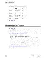
shows the pinouts for an external alarm.
Table 22, Port Circuit Pack and Telephone Pin Designations,
on page 513 provides port circuit pack and
telephone pin designations.
Pinout of C6F Cable
Wire Color
Lead
Designation
Pin
Number
White/Green
L
I
* (High Side)
47
Green
L
I
22
White/Brown
LO
48
Brown
LO* (High Side)
23
White/Slate
LBACK2
49
Slate
LBACK1
24


