G3V4vs/R5vs/R6vs to Avaya Communication Manager
Task List: DEFINITY vs to Avaya Communication Manager
SI Installation and Upgrades
175
June 2004
Alarm connections
The system you are upgrading may use more than 1M and 1m alarm-monitor appearances. If so, use one
of the following methods to redistribute the alarm-monitor appearances:
Redistribution methods
•
Distribute the alarms to the AUXILIARY connector on an R7si EPN.
•
Parallel the alarms to the connections shown in the table above.
•
“Gang” the alarms so that several external devices share the same appearance.
Note that:
Results of ganging method
— When several external devices are ganged to the same appearance, each device loses its
individual identity.
— An alarm on a shared appearance denotes only that one of several devices reported a
problem. Subsequent maintenance effort is needed to determine which device reported the
problem and the nature of the problem.
— The control circuit pack behind the AUXILIARY connector detects external alarms with a
ground-detector chip. Therefore, if you gang several external devices, every device must
be able to return a true relay ground closure to the AUXILIARY connector. (Alternatives
such as a TTL low driver are inadequate.)
Port-network configurations
Consider the following:
•
Every DEFINITY si port-network configuration holds 1 PPN. This can be either a multicarrier or
single-carrier cabinet.
•
Larger configurations can contain either 1 or 2 EPNs.
•
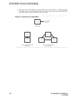
As shown in
si port-network configurations
, the 3 main port-network configurations include:
— Basic system that holds only a PPN
— Directly connected systems that hold:
•
2 port networks (PPN and EPN) connected directly together
•
3 port networks (PPN and two EPNs) connected directly together
•
Upgrading a System 75 system to an R7si or later system offers an optional 2nd and 3rd port
network.
Table 6: AUXILIARY connector appearances
System
Alarm monitor appearances
System 75 XE
1M, 1m, 2M, 2m, 3M, 3m, 3W
R 7si
1M, 1m only


