Connecting and Handling Fiber Optic Cables
LASER Product
SI Installation and Upgrades
763
June 2004
Connecting and Handling Fiber Optic
Cables
Signals between the cabinets composing the system are carried by fiber optic cables. To accomplish this,
the electronic signals at the connectors on the back of a cabinet must be converted into optical signals,
and optical signals from another cabinet must be converted back into electronic signals. Opto-electronic
devices (lightwave transceivers) provide this interface.
LASER Product
The Avaya Media Gateway may contain a Class 1 LASER device if single-mode fiber optic cable is
connected to a remote Expansion Port Network (EPN). The LASER device operates within the following
parameters:
•
Maximum Power Output: -5 dBm
•
Wavelength: 1310 nm
•
Mode Field Diameter: 8.8 micrometers
CLASS 1 LASER PRODUCT
IEC 825 1993
CAUTION:
Use of controls or adjustments or performance of procedures other than those specified
herein may result in hazardous radiation exposure.
Contact your Avaya representative for more information.
Detailed Information
See
Optical Cross-Connect Hardware
on page 763 for hardware details.
See
Cleaning Fiber Optic Cables
on page 768 for cleaning instructions.
Optical Cross-Connect Hardware
Optical cross-connects consist of Lightguide Interconnect Units (LIUs) with lightguide troughs in
between them.
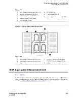
Figure 300, Typical Optical Lightguide Interconnect Unit,
on page 764 shows a typical
LIU. One LIU terminates the incoming cables and the other terminates the outgoing cables. A fiber optic
patch cord or jumper is used to connect the circuits. Circuits can be rerouted the same as on 110-type

