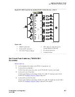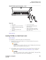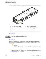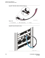
Installing the Stratum 3 Clock
Task List: Install the Stratum 3 clock
SI Installation and Upgrades
695
June 2004
3
Attach the lug to the receptacle cover. Be sure the lug and cabinet ground wires connect to
separate screws on the receptacle cover.
4
Route the ground wire to the DC power plant and connect to DISCH GRD inside the cabinet.
Connect Stratum 3 Clock DC Power
Return to Task List
1
Set the clock cabinet circuit breaker at the DC power plant OFF.
2
At the clock cabinet, connect a 6 AWG (#40) (16 mm
2
) ground wire to the -48V terminal on the
terminal strip.
3
At the clock cabinet, connect a 6 AWG (#40) (16 mm
2
) wire to the -48VRTN terminal on the
terminal strip.
4
Route the wires out of the cabinet and to the DC power plant.
5
At the DC power plant, connect the -48V wire to the DC OUTPUT circuit breaker.
6
At the DC power plant, connect the -48VRTN wire to the DISCH GRD bar.
Return to Task List
Set the Clock Options
Return to Task List
There are four sets of option switches on the clock.
1
Set the options on the Clock Input (CI) circuit pack according to
CI Option Switch Settings
on
page 695.
2
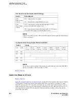
Set the options on the Stratum 3 Clock (ST3) circuit pack according to
ST3 Clock Circuit Pack
Option Switch Settings
on page 696.
3
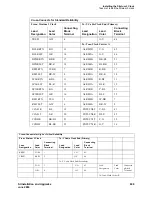
Set the options on the Composite Clock Timing Output (TOCA) circuit pack according to
Composite Clock Timing Output (TOCA) Circuit Pack
on page 696.
4
Set the Stratum 2/Stratum 3 switch to the STRATUM 3 position.
CI Option Switch Settings
Switc
h
Function
Position
1
T1 Select
OFF = enable (default)
ON = disable
2
CC Select
OFF = enable
ON = disable (default)
3
Framing Select
OFF = ESF
ON = D4 (default)
4
BX.25
OFF = enable
ON = disable (default)

