Test the System
LED Indicators
490
SI Installation and Upgrades
June 2004
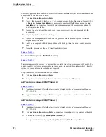
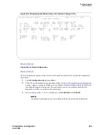
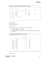
Figure 183: Sample System Configuration Screen
—
Page 1
Return to Task List
Test Time Division Multiplexing Bus in Processor Port Network
Return to Task List
1
Type
test tdm port-network 1
and press Enter.
2
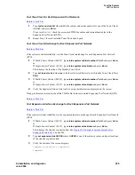
Verify the screen displays the results of this test. See
Figure 184, Sample Test Results for TDM
Bus Port Network 1,
on page 491.
3
If the result is
FAIL
for any test, check the connectors of the TDM bus cables in Processor Port
Network (PPN) 1.
list configuration all
Page 1
SYSTEM CONFIGURATION
Board Assigned Ports
Number Board Type Code Vintage u=unassigned t=tti p=psa
01A01 EXPANSION INTRFC TN570D 000001
01A03 DID TRUNK TN459B 000004 u u u u u u u u
01A04 DID TRUNK TN436B 000004 u u u u u u u u
01A07 TIE TRUNK TN439 000004 u u u u
01A09 ANNOUNCEMENT TN750 000007 01 02 03 04 05 06 07 08
09 10 11 12 13 14 15 16
01B01 EXPANSION INTRFC TN570D 000009
01B02 TONE DETECTOR TN748D 000002 01 02 03 05 06 07
01B03 DATA LINE TN726B 000012 u u u u u u u u
01B08 BRI LINE TN556D 000003 u u u u u u u u
u u u u u u u u
u u u u u u u u
01C01 ANALOG LINE TN746B 000006 u u u u u u u u
u u u u u u u u
press CANCEL to quit -- press NEXT PAGE to continue


