UPS Installation for SCC1 EPN A-Carrier Cabinet
Task List: Install UPS
786
SI Installation and Upgrades
June 2004
6
Plug the UPS into a 120 VAC NEMA 5-15R receptacle.
7
Press and hold the OUTPUT ON button on the UPS until you hear a beep. The INPUT ON and
OUTPUT ON LEDs light up.
8
Program the UPS communication interface port for AS400 mode. Refer to the UPS Site
Preparation, Installation and Operator’s Manual (167-405-120).
Return to Task List
Wire the 700A8 Plug
Return to Task List
1
Cut a piece of 24AWG (2 twisted pairs) wire long enough to reach from the rear of the UPS to the
110 cross-connect field.
2
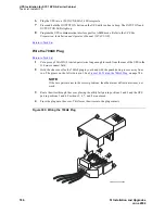
Hold the clear cover for the 700A8 plug in your hand with the punch down grooves away from
you. The groove on the left side is pin 1. See
Figure 303, Wiring the 700A8 Plug,
on page 786.
NOTE:
If the wire pairs are not in the correct positions, then the alarm verification test may not
work.
3
Route the wires through the cover, placing the utility fail pair in positions 1 and 2 and the UPS
pair in positions 5 and 6. Positions 3, 4, 7, and 8 are not used.
4
Press the plug onto the cover. This forces the wires into the plug contacts.
Figure 303: Wiring the 700A8 Plug
1
3
5
2
4
6
7 8
1
2
pldf700a KLC 092899
3
4

