Install and Connect MCC1 (Multicarrier) Cabinet
Task List: Connect AC power and ground
338
SI Installation and Upgrades
June 2004
2
At the bottom rear of the PPN cabinet, connect a 6 AWG (#40) (16 mm
2
) CABINET GROUND
wire to the cabinet ground block. See
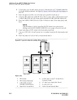
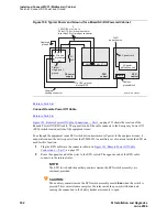
Figure 90, Typical Cabinet Grounding Wiring Diagram,
on
page 338.
3
Route the opposite end of the wire to the single-point ground block and connect.
4
At the first EPN cabinet (if provided) DC Power Cabinet, connect a the 6 AWG (#40) (16 4 mm
2
)
CABINET GROUND wire to the cabinet ground terminal block GROUND DISCHARGE bar.
5
Route the CABINET GROUND wire to Control Cabinet and connect to the single-point ground
block.
NOTE:
If the EPN cabinet is located remote from the PPN cabinet (in a separate room or
building), route the EPN CABINET GROUND wire to an approved protective ground.
6
Repeat connecting each EPN cabinet to the single-point ground block.
7
Connect a 6 AWG (#40) (16 mm
2
) ground wire to an unused terminal on the single-point ground
block.
8
Route the ground wire to the AC load center ground and connect.
Figure 90: Typical Cabinet Grounding Wiring Diagram
Figure notes
1
PPN Cabinet
2
EPN Cabinet (if Installed)
3
6 AWG (#40) (16 mm
2
)
CABINET GROUND Wire
4
Single-Point Ground Block
5
6 AWG (#40) (16 4 mm
2
) Ground Wire to
Approved Ground
6
AC Load Center Single-Point Ground
7
Over 50 ft (15.2 m)
8
Cabinet Ground Terminal Block
6
1
2
2
3
3
3
5
widfspgb KLC 100297
7
4
8
8
8


