G3V4vs/R5vs/R6vs to Avaya Communication Manager
Task List: DEFINITY vs to Avaya Communication Manager
SI Installation and Upgrades
171
June 2004
Disassemble the G3V4vs System [from
G3V4vs/R5vs/R6vs]
Return to Task List
1
Remove any unused 25-pair cables from the rear of the system.
2
Loosen the 4 shoulder screws that hold the cabinet to the mounting plate (see
Figure 8, Exploded
view of DEFINITY vs cabinet,
on page 171).
3
Remove the locking screw that holds the cabinet to the center of the mounting plate.
4
Return the system cabinet to its locked operating position.
5
Align the 4 shoulder screws with the keyhole slots and remove the cabinet from the mounting
plate.
6
Remove the 5 lower wood screws from the wall plate and loosen the top 2 wood screws.
7
Remove the mounting assembly.
8
Remove the top 2 wood screws.
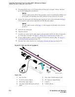
Figure 8: Exploded view of DEFINITY vs cabinet
Return to Task List
Figure notes
1
Shoulder screws
2
Compact single-carrier cabinet
3
Plywood sheet
4
Wall-mounting plate with keyhole slots
5
Cabinet support bracket
6
Locking screws on spring-loaded housing
3
4
5
1
6
2
g3vs-2 LJK 030996


