Install and Wire Telephone Power Supply
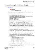
Important Warning for 1145B Power Supply
554
SI Installation and Upgrades
June 2004
•
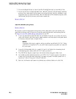
Discard discharged batteries as soon as possible. Discharged batteries are more likely to leak.
•
Do not store batteries in high temperature areas. Batteries stored in a cold environment should be
protected from condensation during storage and warming. Batteries should be stabilized at room
temperature prior to use after cold storage. Do not install batteries if the manufacturing date on the
label indicates that the batteries are more than six months old.
Return to Task List
Install the Wall-Mounting Plates
Return to Task List
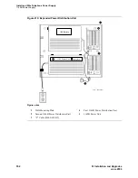
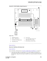
The top plate is used for mounting the back-up battery. The bottom plate is used to mount the power
supply and distribution units. The plates can be rack-mounted using standard rack-mounting brackets.
See
Figure 220, 1145B/1146B Mounting Arrangement,
on page 555.
1
Locate one plate directly below the other one such that the AC power cord (6.5 feet or 2 meters)
reaches the electrical outlet from a power supply mounted on the bottom plate. Both plates should
be located so the raised letters are right side up.
NOTE:
A maximum of four power supplies can be powered from one dedicated 110 VAC, 20 amp
(or 230 VAC, 15 amp) feeder. Use only unswitched receptacles (receptacles not connected
to a wall switch).
2
Secure the wall mounting plates to a standard 3/4 inch (2 cm) thick plywood mounting board.
Each mounting plate comes with four #10 x 1/2-inch wood screws.
3
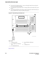
The 1145B Power Supply is snap-fit onto the bottom wall mounting plate without tools.
4
An installer-provided insulated ground wire, 16 AWG (#12) (1.2 mm
2
) or greater, is required to
connect the power supply frame ground lug to an approved ground. The frame ground screw is
located next to the AC receptacle, to the left of the unit.
5
Mark the Unit Number and Connectivity information on the front label next to the LEDs.

