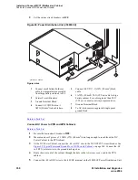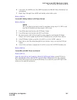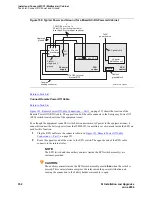
Install and Connect MCC1 (Multicarrier) Cabinet
Task List: Connect DC Power and Ground
354
SI Installation and Upgrades
June 2004
Connect External Alarm Cable
Return to Task List
1
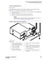
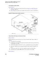
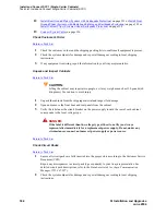
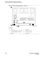
Plug the external alarm cable into the connector shown in
Figure 103, External Alarm Cable
Connection,
on page 354.
2
Route the opposite end of the cable to the MDF. The alarm cable is connected to the MDF later.
Figure 103: External Alarm Cable Connection
Check Commercial Power and Connect AC Power
Return to Task List
Before powering up the system, check the AC power using a KS-20599 digital voltmeter (DVM) (or
equivalent).
1
Set the DVM to the 250 volt range.
2
Carefully measure the voltage between the hot and neutral side of the receptacle. The neutral wire
is white, the hot wire is black.
3
Verify the meter reads 106 to 128 VAC. If not, have a qualified electrician correct the problem.
4
Measure the voltage between the neutral and ground side of the receptacle. The ground wire is
green.
5
Verify the meter reads 0 VAC. If not, have a qualified electrician correct the problem.
6
Set all cabinet power modules OFF. Plug the AC power cable into the receptacle.
Return to Task List
Connect RPO
cable here (J21)
Connect external
alarm cable here
(J18)
Carrier
circuit
breakers
psdf002 CJL 081596
External
alarm cable
Pin 6 (-RPO)
Pin 2 (+RPO)


