Install and Wire Telephones
DS1 Tie Trunk Example
SI Installation and Upgrades
509
June 2004
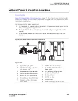
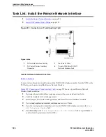
Figure 197: Typical Connections to Channel Service Unit
Figure notes
1
Connector to DS1 Interface Circuit Pack
2
C6C Cable (For Distances Over 50 Feet
(15.24 m), Use C6E Cable(s))
3
T1 Channel Service Unit (CSU) 3150
Shown
4
T (Tip)
5
R (Ring)
6
T1 (Tip 1)
7
R1 (Ring 1)
8
1.544 Mbps Digital Service
Interface
9
To T1 Carrier
DS1 Cables
Connector Cable
Description and Usage
C6C connector cable
50-foot (15.2 m) shielded cable equipped with a 50-pin male
connector on one end and a 15-pin male connector on the other end.
Use this cable to connect a DS1 tie trunk circuit pack to a Channel
Service Unit (CSU).
C6D connector cable
50-foot (15.2 m) shielded cable equipped with a 50-pin male
connector on each end.
Use this cable to connect a DS1 tie trunks in collocated cabinets.
C6E connector cable
100-foot (30.5 m) shielded cable equipped with a 50-pin male
connector on one end and a 50-pin female connector on the other
end.
Use this cable as an “extension” cable between the DS1 tie trunk
circuit pack and other connector cables.
C6F connector cable
50-foot (15.2 m) shielded cable equipped with a 50-pin male
connector on one end and a three inch (7.62 cm) stub on the other
end.
Use this cable to connect the DS1 tie trunk circuit pack to channel
multiplexers requiring hardwired connections.
0012_1 RBP 062696
AUX PORT COM PORT
MODEM
DTE
NETWORK
POWER

