Install and Connect SCC1 (Single-Carrier Cabinets)
Task List: Install a J58890CG DC Power Distribution Unit
SI Installation and Upgrades
375
June 2004
Making DC Power Connections
A 30 foot (9 m) cable connects to each cabinet. A special connector on one end of the cable is plugged
into the cabinet power connector. The cable must be cut to length and terminated inside the J58890R DC
Power Cabinet.
Each rectifier assembly can supply up to 50 Amps of DC current. A minimum of two rectifiers are
installed in each DC Power Cabinet to supply a total of 100 Amps. A third rectifier assembly can be
installed and is used as a backup (N+1). Each Single-Carrier Cabinet can pull up to 18 Amps. Up to three
DC Power Cabinets can be stacked to supply power to Single-Carrier Cabinet stacks.
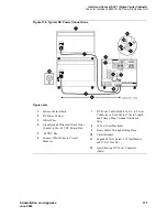
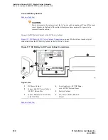
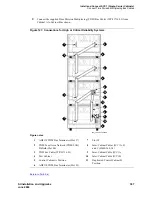
Figure 114, Typical DC Power Connections,
on page 377 shows a typical power and ground layout for a
DC-powered system without a J58890CG DC Power Distribution Unit.
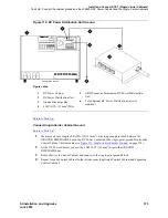
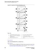
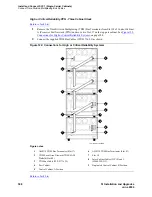
Figure 115, Connections Using
DC Power Distribution Unit,
on page 378 shows a typical power and ground layout for a DC-powered
system containing a DC power distribution unit.
NOTE:
If the distance between the DC Power Cabinet(s) is greater than 30 feet (9 m), use the
Task List: Install a J58890CG DC Power Distribution Unit
on page 375.
Task List: Install a J58890CG DC Power Distribution
Unit
•
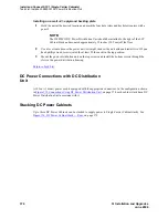
Install on a wall without a plywood backing plate
on page 375
•
Installing on a wall with a plywood backing plate
on page 376
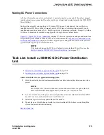
Install on a wall without a plywood backing plate
1
Hold the unit at the desired location and mark the four hole (slots and keyholes) centers with a
pencil.
NOTE:
The J58890CG DC Power Distribution Unit should be installed to the right of the SCC
Cabinet Stack and mounted approximately 12 inches (30.5 cm) off the floor.
2
Use a level to make sure the power unit is straight, then set the unit aside and install four ZINC
drywall “screw-in” anchors rated for at least 50 lbs each.
3
Install the top two screws supplied with the zinc anchors.
4
Mount the power distribution unit on the top screws and install the bottom screws through the
slots in the power distribution housing.
Return to Task List


