9-4
Chapter 9
Operating Instructions
・
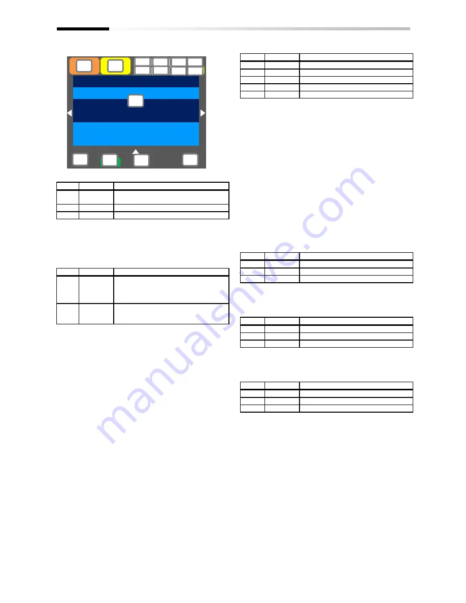
Sections of display screen on the operator keypad
<a> Power status display
No.
Indication
Description
a1
(None)
There is input to the main power
supply/control power supply.
a2
CTRL
There is input to the control power supply.
a3
24V
The device runs with 24V input to P+/P-.
(Tips)
・
Indicates the status of power input. When CTRL or 24V
is displayed, main power is not input, which makes
operation impossible. Check the power supply.
<b> Display of SET function operation status
No.
Indication
Description
b1
M1
The [SET] terminal is not selected or the
[SET] terminal is selected but the function
is disabled. (common setting and first
setting are enabled)
b2
M2
The [SET] terminal is selected and the
function is enabled. (common setting and
second setting are enabled)
・
If the [SET] terminal is not used, M1 is displayed. If the
center of parameter is “-” (common setting such as [AC-
01]) or “1” (first setting such as [AA111]), the setting is
enabled, and “2” (second setting such as [AA211]) is
ignored.
<c> Selection of parameter display
No.
Indication
Description
c1
(None)
All-parameter display mode.
c2
UTL
Individual-function display mode.
c3
USR
User-setting display mode.
c4
CMP
Data-comparison display mode.
c5
MON
Monitor display mode.
(Tips)
・
This section is displayed when the display limit function
is working. If there is a hidden parameter, change the
setting in [UA-10].
<d> Display of monitor screen No.
(Tips)
・
Displays the screen number of each monitor. When
making inquiries, please tell us the number of monitor
displayed on your screen. The list of monitor screen
numbers is shown in the next page.
<e> STO function display
(Tips)
・
If the function is displayed, it means the current is shut
off.
* For details of the STO function display, please contact us.
<f> Display of control command mode
No.
Indication
Description
f1
(None)
The speed control mode.
f2
TRQ
The torque control mode.
f3
POS
The position control mode.
(Tips)
・
Indicates the mode of control operation.
<g> Display of EzSQ operation mode
No.
Indication
Description
g1
(None)
EzSQ is not selected.
g2
Ez_S
The EzSQ program is stopped.
g3
Ez_R
The EzSQ program is working.
(Tips)
・
You can check whether the EzSQ function is working.
<h> Display of special function status
No.
Indication
Description
h1
(None)
The device is not in the special status.
h2
AUT
The device is auto-tuning.
h3
SIM
The device is in the simulation mode.
(Tips)
・
If the function is displayed, it means that the device is in
the special state.
Menu
Optional
device
0.00Hz
oFW
STOP
M1
H03
Output Frequency
0.00 Hz
FA-01
Main speed command (Operator keypad)
0.00 Hz
[0.00-60.00]
NRDY
CTR
SIM Ez_S
UTL
TRQ
STO
(A)
(B)
(C)
(D)
(E)
(F)
(G)
<a>
<b>
<c>
<d>
<e>
<f>
<g>
<h>
Summary of Contents for SJ Series
Page 39: ...5 4 Chapter 5 Included Items Memo ...
Page 55: ...6 16 Chapter 6 Installation Memo ...
Page 91: ...7 36 Chapter 7 Wire Connection and Optional Devices Memo ...
Page 135: ...9 40 Chapter 9 Operating Instructions Memo ...
Page 145: ...10 10 Chapter 10 Test Run Memo ...
Page 159: ...12 2 6 Chapter 12 Inverter Functions Memo ...
Page 169: ...12 3 10 Chapter 12 Inverter Functions Memo ...
Page 195: ...12 5 8 Chapter 12 Inverter Functions Memo ...
Page 217: ...12 8 12 Chapter 12 Inverter Function Memo ...
Page 287: ...12 10 32 Chapter 12 Inverter Functions Memo ...
Page 303: ...12 11 16 Chapter 12 Inverter Functions Memo ...
Page 349: ...12 15 8 Chapter 12 Inverter Function Memo ...
Page 395: ...12 17 34 Chapter 12 Inverter Functions Memo ...
Page 397: ...12 18 2 Chapter 12 Inverter Functions Memo ...
Page 415: ...12 19 18 Chapter 12 Inverter Function Memo ...
Page 581: ...15 10 Chapter 15 Optional Cassettes Memo ...
Page 591: ...16 10 Chapter 16 ProDriveNext EzSQ Memo ...
Page 642: ...18 49 Chapter 18 Tips FAQ Troubleshooting Memo ...
Page 650: ...19 8 Chapter 19 Maintenance and Inspection Memo ...
Page 781: ...Appendix 1 70 Appendix 1 List of Parameters Memo ...


