12-10-2
Chapter 12
Inverter Functions
• For PID control, you can select feed-forward
control to attempt stabilizing disturbance in
advance, in addition to feedback control to
stabilize disturbance.
• To control output frequency sent to the motor by
the PID function, selection of PID1-4 and setting of
frequency command are required.
• In the soft-start function, operating normally for a
certain period of distance at the start can raise
output automatically and then shift to PID control.
See "12.10.5 PID Soft-Start Function".
• Sleep mode operation, which is more energy
saving, can be set for when the flow rate or air
volume is increased. See "12.10.6 PID Sleep
Condition Selection Function".
• During PID operation, PID functions are disabled
and normal output is performed with the command
selected as a target value, while the input terminal
function [PID] signal is ON.
• Multi-layer command by PID control command is
feasible.
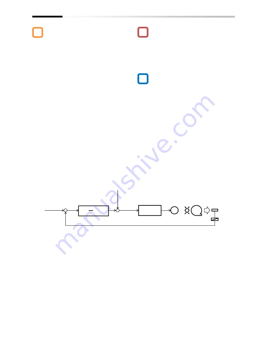
Basic composition of PID control
• In the case of controlling the motor by PID control,
frequency command destination needs to be set to
PID output.
• The upper/lower limiter function operates for
command frequency by PID output. It does not
operate for PID target value.
e.g.) Follow the steps below to perform simple PID
control by inputting a target value [Ai1] and a
feedback (FB) value [Ai2] from where parameters
are default.
[1]Set [AH-01] to 01 (enable)
[2] Set 15 (PID calculation) to the main speed
command selection [AA101]
[3] Set 01 (Ai1) to the PID1 target value 1 input
destination [AH-07]
[4] Set 02 (Ai2) to the PID1 FB 1 input destination
[AH-07]
[5] Set the PID gain of PID1 to [AH-61] to [AH-63]
[6] Put the command set to operation command
selection [AA111] and start PID control
A
!
▼
Target
value
0
~
10V
4
~
20mA
Sensor
Inverter
Normal control
Operation
amount
fs
M
=
Transducer
Feedback 0 to 10V
4
∼
20mA
+
-
Deviation
ε
Kp (1+ +Td
・
S)
1
Ti•S
+
+
Feed-forward
Disable
0
∼
10V
4
∼
20mA
-10
∼
10V
PID calculation
Kp: Proportional gain Ti: Integral time Td: Differential time s: Operator
ε
: Deviation
Ki: Integral gain setting (Ki=Ti/Kp) Kd: Differential gain setting (Kd=Kp×Td)
Summary of Contents for SJ Series
Page 39: ...5 4 Chapter 5 Included Items Memo ...
Page 55: ...6 16 Chapter 6 Installation Memo ...
Page 91: ...7 36 Chapter 7 Wire Connection and Optional Devices Memo ...
Page 135: ...9 40 Chapter 9 Operating Instructions Memo ...
Page 145: ...10 10 Chapter 10 Test Run Memo ...
Page 159: ...12 2 6 Chapter 12 Inverter Functions Memo ...
Page 169: ...12 3 10 Chapter 12 Inverter Functions Memo ...
Page 195: ...12 5 8 Chapter 12 Inverter Functions Memo ...
Page 217: ...12 8 12 Chapter 12 Inverter Function Memo ...
Page 287: ...12 10 32 Chapter 12 Inverter Functions Memo ...
Page 303: ...12 11 16 Chapter 12 Inverter Functions Memo ...
Page 349: ...12 15 8 Chapter 12 Inverter Function Memo ...
Page 395: ...12 17 34 Chapter 12 Inverter Functions Memo ...
Page 397: ...12 18 2 Chapter 12 Inverter Functions Memo ...
Page 415: ...12 19 18 Chapter 12 Inverter Function Memo ...
Page 581: ...15 10 Chapter 15 Optional Cassettes Memo ...
Page 591: ...16 10 Chapter 16 ProDriveNext EzSQ Memo ...
Page 642: ...18 49 Chapter 18 Tips FAQ Troubleshooting Memo ...
Page 650: ...19 8 Chapter 19 Maintenance and Inspection Memo ...
Page 781: ...Appendix 1 70 Appendix 1 List of Parameters Memo ...


