14-24
Chapter 14
RS485 Communication
14.5.4
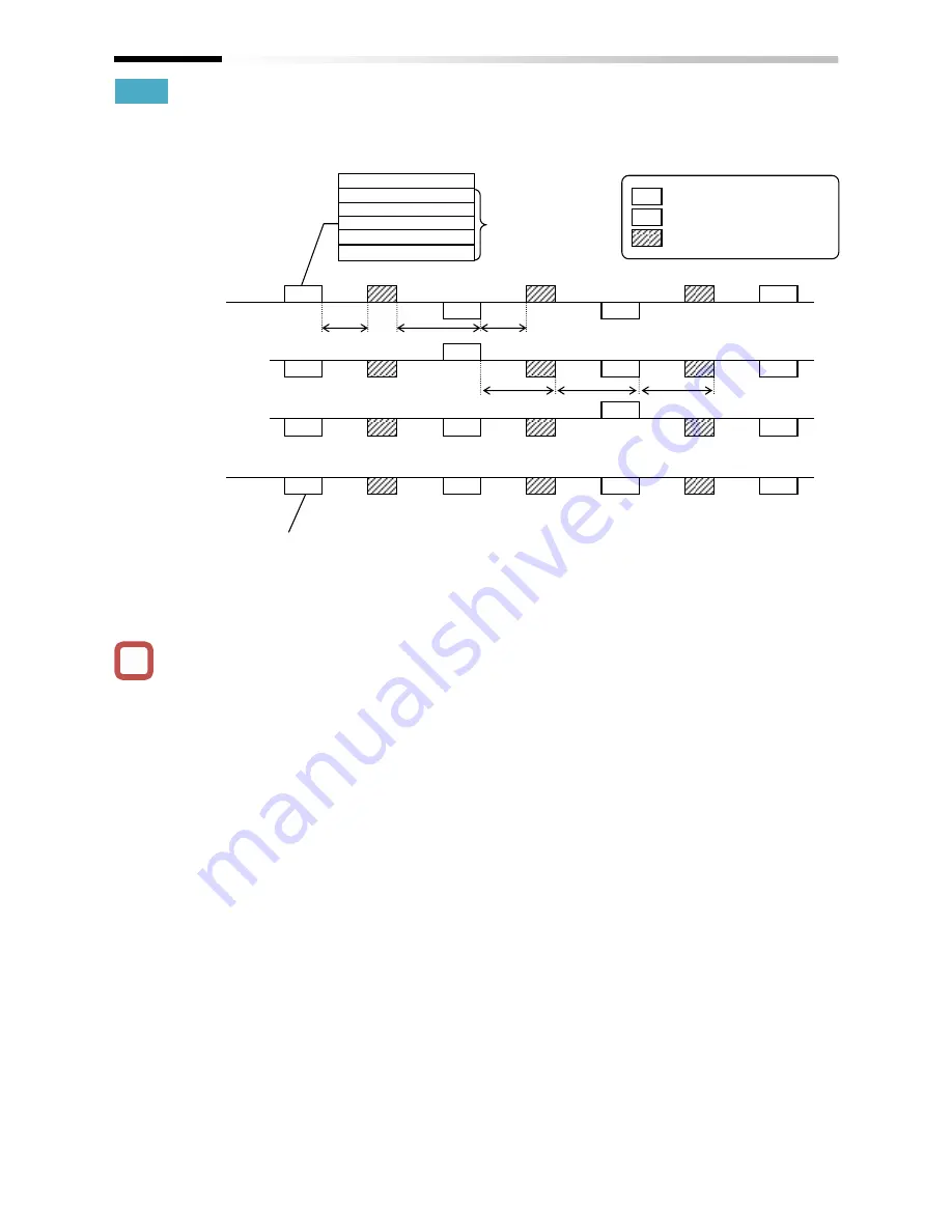
Examples of EzCOM communication
• Shown below is communication sequences of
inverters with station numbers 01 to 04 (four
inverters in total), where the inverters 01 to 03 are
designated as master inverters.
•
Communication timeout time [CF-06] for the
controlling inverter, make sure to set value other
than 0 (1 second or longer is recommended).
Otherwise, the EzCOM function will stop when the
communication is timed-out and data from a master
inverter cannot be received. When the EzCOM
function is stopped, reset the controlling inverter by
turning on the power again or by resetting with the
[RS] terminal.
• If the controlling inverter is a master inverter, a
master switching instruction is transmitted after the
master inverter transmits data followed by a silent
interval + communication waiting time [CF-07]
(aforementioned t1).
• If an inverter other than the controlling inverter is a
master inverter, a master switching instruction is
transmitted after the data from the master inverter
is received followed by a silent interval +
communication
waiting
time
[CF-07]
(aforementioned t2).
• The timer of communication timeout starts counting
from the start of reception waiting. If data reception
isn’t completed within a set time, the
communication will be timed-out (aforementioned
t3), and the the inverter behaves in accordance
with the communication error selection [CF-05].
!
Controlling
INV (01)
Transmitting
Receiving
INV (02)
Transmitting
Receiving
Transmitting
Receiving
Transmitting
Receiving
M
S
S
S
M
S
S
S
M
S
S
S
M
S
S
S
INV (03)
INV (04)
Station No. Register Data
02 xxxx xxxx
02 xxxx xxxx
03 xxxx xxxx
03 xxxx xxxx
03 xxxx xxxx
Up to five
transmission
destinations can
be designated.
t3
t2
t3
t3
Although all slaves receive data from
a master, if there is no data
addressed to them, the received data
by them will be discarded.
t1: Silent in communication waiting time [CF-07]
t2: Silent in communication waiting time [CF-07]
t3: Communication timeout time [CF-06]
t1
M Transmission data from a
master
S Data received by a slave
Master switching instruction
t3
Summary of Contents for SJ Series
Page 39: ...5 4 Chapter 5 Included Items Memo ...
Page 55: ...6 16 Chapter 6 Installation Memo ...
Page 91: ...7 36 Chapter 7 Wire Connection and Optional Devices Memo ...
Page 135: ...9 40 Chapter 9 Operating Instructions Memo ...
Page 145: ...10 10 Chapter 10 Test Run Memo ...
Page 159: ...12 2 6 Chapter 12 Inverter Functions Memo ...
Page 169: ...12 3 10 Chapter 12 Inverter Functions Memo ...
Page 195: ...12 5 8 Chapter 12 Inverter Functions Memo ...
Page 217: ...12 8 12 Chapter 12 Inverter Function Memo ...
Page 287: ...12 10 32 Chapter 12 Inverter Functions Memo ...
Page 303: ...12 11 16 Chapter 12 Inverter Functions Memo ...
Page 349: ...12 15 8 Chapter 12 Inverter Function Memo ...
Page 395: ...12 17 34 Chapter 12 Inverter Functions Memo ...
Page 397: ...12 18 2 Chapter 12 Inverter Functions Memo ...
Page 415: ...12 19 18 Chapter 12 Inverter Function Memo ...
Page 581: ...15 10 Chapter 15 Optional Cassettes Memo ...
Page 591: ...16 10 Chapter 16 ProDriveNext EzSQ Memo ...
Page 642: ...18 49 Chapter 18 Tips FAQ Troubleshooting Memo ...
Page 650: ...19 8 Chapter 19 Maintenance and Inspection Memo ...
Page 781: ...Appendix 1 70 Appendix 1 List of Parameters Memo ...


