12-14-14
Chapter 12
Inverter Function
12.14.9
Starting after applying servo-lock
• How to start operation after having the rotating
motor stopped and secured it
• Before outputting the frequency to the motor,
perform the servo-lock to stop the motor rotating.
And then, start operation.
• To apply DC braking for starting (servo-lock
control), the following settings are required:
- [AA121] Control mode (see the right section)
- Set [AF101] DC braking selection to 01
- Set [AF102] Braking mode selection to 01 or
02.
- Set [AF109] DC braking time for starting to
other than 0.0
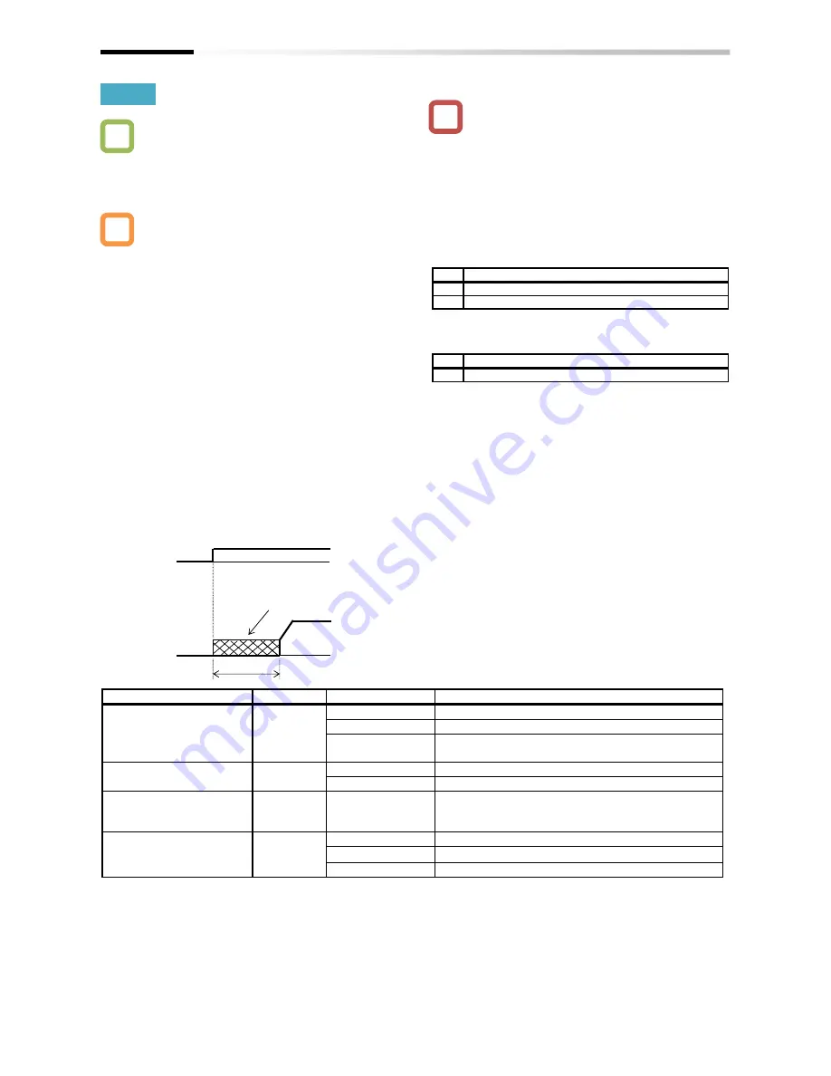
• If the DC braking for starting (servo-lock control) is
enabled, DC braking (servo-lock control) will be
performed after the operation command is given,
for the period of time set as DC braking time for
starting [AF109].
Example of a case where the servo-lock control at
starting is enabled
Parameter
• Depending on the set braking force, the carrier
frequency may automatically go down to protect
the inverter.
• To use the servo-lock control, it is necessary to set
[AA121] Control mode. If the applicable control
mode is not selected, the inverter will operate as if
[AF102] has been set to 00: DC braking.
(1) When [AF102] Braking mode selection is set to
01: Speed servo-lock
No.
[AA121] Control mode
1
09: Zero-speed range sensorless vector control
2
10: Vector control with sensor
(2) When [AF102] Braking mode selection is set to
02: Position servo-lock
No.
[AA121] Control mode
1
10: Vector control with sensor
• For [AA121] Control mode and [AA123] Vector
control mode selection, it is necessary to set .
See "12. 9 Selecting the Motor Control Method
According to Motor and Load".
• The output of the servo-lock control is
automatically calculated according to the selected
control mode.
Item
Parameter
Data
Description
DC braking selection
[AF101]
00
Internal DC braking: Disabled
01
Internal DC braking: Enabled
02
Internal DC braking: Enabled (The braking operates
only with the set braking frequency.)
Braking mode selection
[AF102]
01
Enables the speed servo-lock.
02
Enables the position servo-lock.
DC braking time for
starting
[AF109]
0.0~60.0(s)
Valid when the internal DC braking is enabled.
Starts the servo-lock when the operation command is
turned on.
Control mode
[AA121]
08
Sensorless vector control
09
Zero-speed range
sensorless vector control
10
Vector control with sensor
Q
A
!
[AF109]
DC braking (servo-lock
control)
FW
Output
frequency
ON
Summary of Contents for SJ Series
Page 39: ...5 4 Chapter 5 Included Items Memo ...
Page 55: ...6 16 Chapter 6 Installation Memo ...
Page 91: ...7 36 Chapter 7 Wire Connection and Optional Devices Memo ...
Page 135: ...9 40 Chapter 9 Operating Instructions Memo ...
Page 145: ...10 10 Chapter 10 Test Run Memo ...
Page 159: ...12 2 6 Chapter 12 Inverter Functions Memo ...
Page 169: ...12 3 10 Chapter 12 Inverter Functions Memo ...
Page 195: ...12 5 8 Chapter 12 Inverter Functions Memo ...
Page 217: ...12 8 12 Chapter 12 Inverter Function Memo ...
Page 287: ...12 10 32 Chapter 12 Inverter Functions Memo ...
Page 303: ...12 11 16 Chapter 12 Inverter Functions Memo ...
Page 349: ...12 15 8 Chapter 12 Inverter Function Memo ...
Page 395: ...12 17 34 Chapter 12 Inverter Functions Memo ...
Page 397: ...12 18 2 Chapter 12 Inverter Functions Memo ...
Page 415: ...12 19 18 Chapter 12 Inverter Function Memo ...
Page 581: ...15 10 Chapter 15 Optional Cassettes Memo ...
Page 591: ...16 10 Chapter 16 ProDriveNext EzSQ Memo ...
Page 642: ...18 49 Chapter 18 Tips FAQ Troubleshooting Memo ...
Page 650: ...19 8 Chapter 19 Maintenance and Inspection Memo ...
Page 781: ...Appendix 1 70 Appendix 1 List of Parameters Memo ...


