12-13-20
Chapter 12
Inverter Function
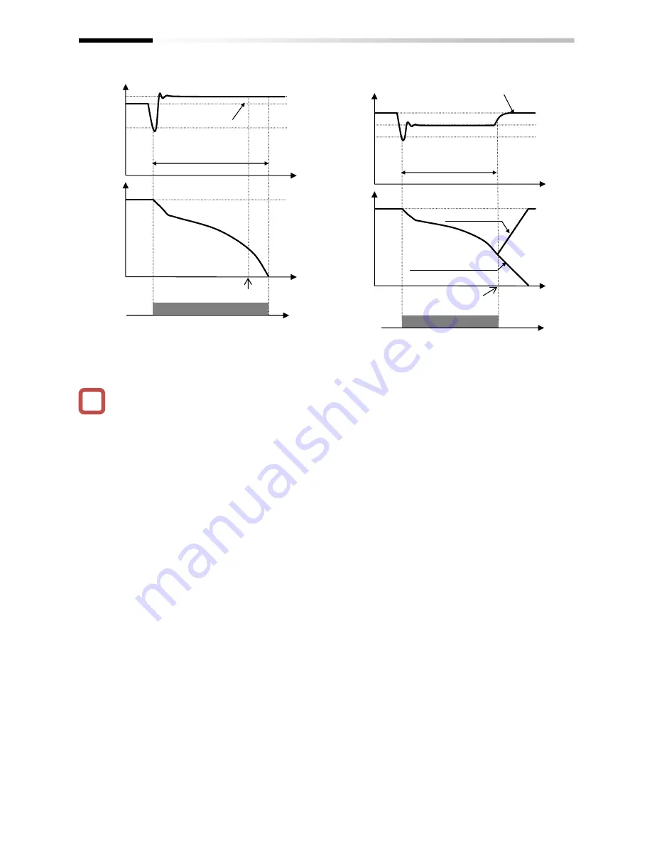
• Keep the settings for [bA-31] and [bA-32] to the
undervoltage recovery level (P-N voltage 180 V
(200 V class), 360 V (400 V class)) or higher. The
function will not be activated in case of
undervoltage.
• Make setting so that [bA-31] will be lower than
[bA-32]. If the difference between the settings for
[bA-31] and [bA-32] is great, setting the
proportional gain [bA-37] to be too large may
cause sudden acceleration immediately after this
function is activated and may cause overcurrent.
• When [bA-30] is 02 or 03, PI control is performed
so that the internal DC voltage will be constant.
• Setting the proportional gain [bA-37] to be large will
accelerate the response. However, setting it to be
too large will dissipate the control, tending to cause
tripping.
• Setting the integral gain [bA-38] to be short will
accelerate the response. However, setting it to be
too short will also tend to cause tripping.
• If the proportional gain [bA-37] is small, the motor
will trip due to undervoltage because the voltage
will drop immediately after the function is activated.
• If you would like to retry even if the power failure
may be relatively long, supply the P-N voltage to
R0 and T0.
!
Main Circuit
P-N Voltage
(V)
Time
Time
Under Constant DC
Voltage Control
[bA-30] = 03
[bA-30] = 02
(Deceleration and stop)
Power recovered
Main Circuit DC Voltage
[bA-32]
[bA-31]
(Ex. 2)
Power
Recovery
ON
(Ex. 1)
Main Circuit
P-N Voltage (V)
Time
Time
Under Constant DC Voltage Control
[bA-30] = 02 or 03
(Deceleration and stop)
Power recovered
Main Circuit DC
Voltage
[bA-30]
[bA-31]
Note) Depending on the proportional gain and
integral time settings, the main circuit DC
voltage level while the function is being
activated may be lower than [bA-32].
Power Recovery
ON
[IPS] Signal
[IPS] Signal
Time (sec)
Summary of Contents for SJ Series
Page 39: ...5 4 Chapter 5 Included Items Memo ...
Page 55: ...6 16 Chapter 6 Installation Memo ...
Page 91: ...7 36 Chapter 7 Wire Connection and Optional Devices Memo ...
Page 135: ...9 40 Chapter 9 Operating Instructions Memo ...
Page 145: ...10 10 Chapter 10 Test Run Memo ...
Page 159: ...12 2 6 Chapter 12 Inverter Functions Memo ...
Page 169: ...12 3 10 Chapter 12 Inverter Functions Memo ...
Page 195: ...12 5 8 Chapter 12 Inverter Functions Memo ...
Page 217: ...12 8 12 Chapter 12 Inverter Function Memo ...
Page 287: ...12 10 32 Chapter 12 Inverter Functions Memo ...
Page 303: ...12 11 16 Chapter 12 Inverter Functions Memo ...
Page 349: ...12 15 8 Chapter 12 Inverter Function Memo ...
Page 395: ...12 17 34 Chapter 12 Inverter Functions Memo ...
Page 397: ...12 18 2 Chapter 12 Inverter Functions Memo ...
Page 415: ...12 19 18 Chapter 12 Inverter Function Memo ...
Page 581: ...15 10 Chapter 15 Optional Cassettes Memo ...
Page 591: ...16 10 Chapter 16 ProDriveNext EzSQ Memo ...
Page 642: ...18 49 Chapter 18 Tips FAQ Troubleshooting Memo ...
Page 650: ...19 8 Chapter 19 Maintenance and Inspection Memo ...
Page 781: ...Appendix 1 70 Appendix 1 List of Parameters Memo ...


