21-38
Chapter 21
Technical Notes
21.4.4
STO Status Retention Function
The retention function that retains the blocked status of
internal safety path even if STO input is canceled is not
implemented as a safety circuit.
Therefore, if an operation command is input after
cancellation of STO input or STO input is canceled while it
is input, the inverter starts output to the motor.
Hence, to satisfy the requirement about cancellation of
emergency stop specified in EN/IEC60204-1, you need to
take either of the following measures.
(1) At the same time as STO input, set the operation
command to the inverter to stopped status
(2) Configure the system so that STO input to SJ-P1 is
canceled when system reboot is required by the user.
By setting parameters of the main unit, you can select the
following operations. (see 4.7)
(1) Trip the inverter by STO input. In this case, the
inverter is tripped and output is stopped until power is
shut off or the error reset signal for the inverter is
input.
(2) If two STO input systems to the inverter are not input
at the same time, the inverter is shut off and enters
standby mode until STO input for the two systems is
input.
21.4.5
STO Confirmation Signal Output (EDM
Signal)
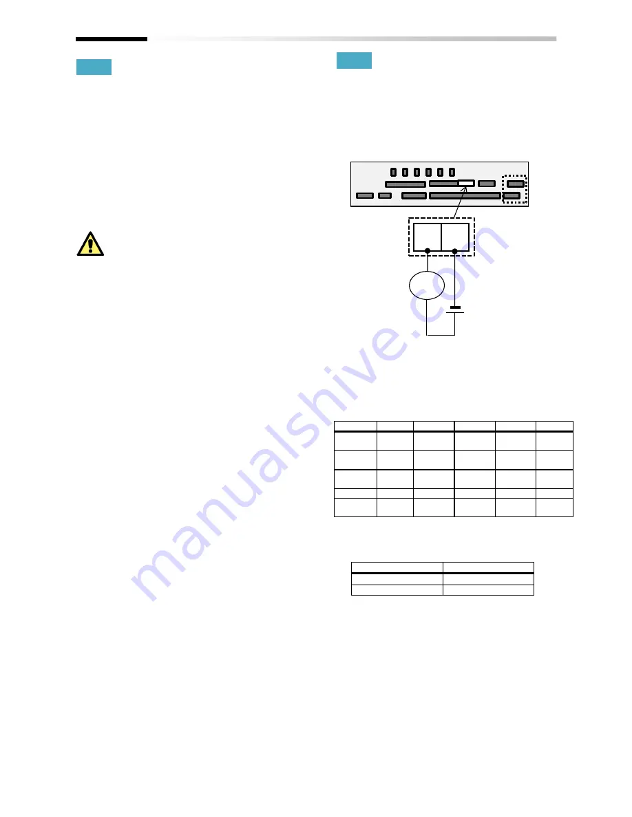
The STO confirmation signal output (EDM output) is the
output signal for monitoring the input status of STO signal
and failure detection status on the internal safety path.
EDM terminal (ED+ / ED-) and wiring example
For operation of ST1/St2 and output of STO confirmation
signal against failure detection status, see the matrix
below. EDM turns ON only when both STO inputs are
correctly input and internal failure is not detected.
Signal matrix
Signal
Status 1 Status 2
Status 3
Status 4 Status 5
ST1 *1)
STO
Operation
permitted
STO
Operation
permitted
*
ST2 *1)
STO
STO
Operation
permitted
Operation
permitted
*
Failure
detection
None
None
None
None
Detected
EDM
ON
OFF
OFF
OFF
OFF
Output to
the motor
Off
Off
Off
Output
permitted
Off
*1) The following table shows the correspondence
between the input status of ST1/ST2 described
in the table above and status of contact points.
Input status
Contact point
STO
OFF
Operation permitted
ON
Control circuit terminal area
ED-
ED+
STO
confirmation
terminal
Duty
Wiring example
Summary of Contents for SJ Series
Page 39: ...5 4 Chapter 5 Included Items Memo ...
Page 55: ...6 16 Chapter 6 Installation Memo ...
Page 91: ...7 36 Chapter 7 Wire Connection and Optional Devices Memo ...
Page 135: ...9 40 Chapter 9 Operating Instructions Memo ...
Page 145: ...10 10 Chapter 10 Test Run Memo ...
Page 159: ...12 2 6 Chapter 12 Inverter Functions Memo ...
Page 169: ...12 3 10 Chapter 12 Inverter Functions Memo ...
Page 195: ...12 5 8 Chapter 12 Inverter Functions Memo ...
Page 217: ...12 8 12 Chapter 12 Inverter Function Memo ...
Page 287: ...12 10 32 Chapter 12 Inverter Functions Memo ...
Page 303: ...12 11 16 Chapter 12 Inverter Functions Memo ...
Page 349: ...12 15 8 Chapter 12 Inverter Function Memo ...
Page 395: ...12 17 34 Chapter 12 Inverter Functions Memo ...
Page 397: ...12 18 2 Chapter 12 Inverter Functions Memo ...
Page 415: ...12 19 18 Chapter 12 Inverter Function Memo ...
Page 581: ...15 10 Chapter 15 Optional Cassettes Memo ...
Page 591: ...16 10 Chapter 16 ProDriveNext EzSQ Memo ...
Page 642: ...18 49 Chapter 18 Tips FAQ Troubleshooting Memo ...
Page 650: ...19 8 Chapter 19 Maintenance and Inspection Memo ...
Page 781: ...Appendix 1 70 Appendix 1 List of Parameters Memo ...


