


Balanced Measurements
R&S
®
ZVA/ZVB/ZVT
1145.1084.12 9.10
E-4
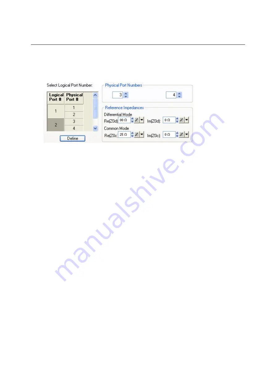
4. Select
Logical Port # 2
and assign the two remaining
Physical Port Numbers,
e.g. 3 and 4.
5. Assign the appropriate differential and common mode reference impedances to logical port no.
2 and Click
Define
.
The
Def Balanced Port
tab shows the balanced port configuration:
6. Connect one balanced port of your DUT to ports 1 and 2 of the network analyzer, the other
balanced port of your DUT to ports 3 and 4 of the network analyzer, in accordance with the
selected reference impedances.
7. Click
OK
to close the
Balanced and Measured Ports
dialog
.
8. Back in the
More S-Parameters
dialog, select the balanced S-parameter that you wish to
measure.
9. Click
OK
to close the
More S-Parameters
dialog and perform the measurement
.
Network (De-)embedding
The
Virtual Transform
menu provides the functions for network embedding and deembedding. The
following examples show how to use the functions.
To add a virtual transformation network to a single-ended port...
Suppose that your DUT is a 2-port DUT with single ended ports.
1. Connect the DUT to your analyzer: For a two-port measurement, connect the DUT between test
ports 1 and 2 of the analyzer.
2. Establish the necessary
Channel
settings (port configuration, sweep range and type etc.) and
select the measured quantities
(Trace – Measure).
3. Click
Channel – Mode – Virtual Transform – Single Port Embedding
to open the
Single Port
Embedding...
dialog.
4. In the dialog, select the
Physical Port
to which you want to add a virtual transformation network
(e.g.
Physical Port 1)
and do one of the following:
5. If you wish to define the added network by an imported set of 2-port S-parameters, select the
2-
Port
transformation network, click
Read Data From File,
and load the parameters from a 2-port
(*.s2p) Touchstone file
.
6. If you wish to define the added network by an equivalent circuit, select the circuit type and
adjust the parameters R, C, and L displayed in the right half of the dialog.
7. Click
Embed DUT
and
Close
the dialog.
The traces of the active channel show the characteristics of the DUT including the virtual transformation
Summary of Contents for 1145.1010.04/05/06
Page 10: ......
Page 20: ......
Page 22: ......
Page 48: ......
Page 70: ......
Page 72: ......
Page 90: ......
Page 92: ......
Page 108: ......
Page 156: ......
Page 162: ......
Page 406: ...Display Menu R S ZVA ZVB ZVT 1145 1084 12 4 244 E 6 Stack Tile Horizontally Tile Vertically...
Page 450: ...Status Reporting System R S ZVA ZVB ZVT 1145 1084 12 5 18 E 1...
Page 462: ......
Page 766: ......
Page 772: ......
Page 792: ......
Page 794: ......
Page 808: ......


