Connecting
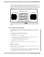
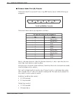
Connect the terminal to the RS-232C connector marked J1 connector in the rear
the Terminal
of the cabinet or to SP1 (above the card cage in front of the cabinet).
When the VP 300 is initially powered up or restarted, it is necessary to establish the
system baud rate in order to print diagnostic messages. Refer to System Startup in
this chapter.
If the system baud rate has already been established, the system header displays.
Otherwise, press
repeatedly to establish the baud rate.
■
System Startup
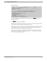
When the VP 300 is loaded or reloaded, the CPU and VCU execute a Boot ROM diagnostic. This
section describes the results of this diagnostic.
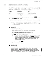
Turn ON your terminal and set the baud rate to any of the valid rates (300, 600, 1200, 2400, 4800,
9600, or 19200). At any of these baud rates, the VP 300 prints or displays the diagnostic status. Turn
ON the power to the cabinet.
Immediately following power up, press
repeatedly to establish the baud rate. If the baud rate
is not established at this time, the system header and diagnostic messages will not print.
Enter
Enter
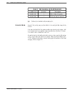
Table 3-6 Power Supply Output Rating and Acceptable
Operating Ranges
Test Point
Nominal Voltage
Acceptable Operating Range (VDC)
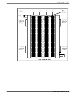
8
7
6
5
4
3
2
1
Ground
–5VC
+5VC
+12VM
–12V
+12V
+5V
Ground
—
–4.50 to –5.50V
4.50 to 5.50V
11.40 to 12.60V
–10.80 to –13.20V
10.80 to 13.20V
4.75 to 5.25V
—
Toshiba VP Systems Release 7.1 July, 1994
INSTALLATION
3-23
Summary of Contents for VP 300
Page 2: ......
Page 10: ......
Page 14: ......
Page 20: ...Toshiba VP Systems Release 7 1 July 1994 ...
Page 52: ...Toshiba VP Systems Release 6 1 February 1993 2 14 Installation and Maintenance Manual ...
Page 56: ...Toshiba VP Systems Release 7 1 July 1994 ...
Page 146: ......
Page 312: ...Toshiba VP Systems Release 7 1 July 1994 ...
Page 314: ......
Page 444: ......
Page 496: ......
Page 542: ......
Page 598: ...Toshiba VP Systems Release 6 1 February 1993 ...
Page 600: ...Toshiba VP Systems Release 6 1 February 1993 ...


