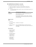
Action
VP 300 Description and Response
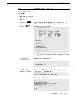
17. @DISKO
The following menu is presented:
18. Choose option 3 —
The following menu is presented:
REPLACE A DISK.
19. Enter the number of the
After several seconds the VP 300 displays:
drive slot to be replaced.
20. Remove the Release 5
Software Diskette #1 from
the FD.
Reload the System
21. Make sure the
configuration backup
diskette is write-enabled.
22. Insert the configuration
backup diskette into the
FD.
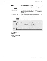
23. Press the lower button
To reload the system.
on the CPU.
DRIVE #N HAS BEEN REPLACED AND IS NOW ACTIVE.
:3
Select drive slot to be replaced: (Empty line = EXIT)
:
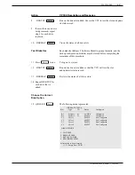
CURRENT STATUS
Slot
Type
ID
Status
Configured
- - - - - - - - - - - - - - - - - - - - - - - - - - - - -
B3
System1
S1
ACTIVE
Configured
B4
System2
– –
INVALID
Configured
C1
Voice1
– –
EMPTY
Not Configured
C2
Voice2
– –
EMPTY
Not Configured
C3
Voice3
– –
EMPTY
Not Configured
C4
Voice4
– –
EMPTY
Not Configured
DISK OPTIONS
1. ADD DISK
2. REMOVE DISK
3. REPLACE A DISK
4. RESTORE SYSTEM
Select option to be performed
(1–5, – Empty line = EXIT)
:
Enter
Toshiba VP Systems Release 7.1
July, 1994
PROCEDURES
6-67
Summary of Contents for VP 300
Page 2: ......
Page 10: ......
Page 14: ......
Page 20: ...Toshiba VP Systems Release 7 1 July 1994 ...
Page 52: ...Toshiba VP Systems Release 6 1 February 1993 2 14 Installation and Maintenance Manual ...
Page 56: ...Toshiba VP Systems Release 7 1 July 1994 ...
Page 146: ......
Page 312: ...Toshiba VP Systems Release 7 1 July 1994 ...
Page 314: ......
Page 444: ......
Page 496: ......
Page 542: ......
Page 598: ...Toshiba VP Systems Release 6 1 February 1993 ...
Page 600: ...Toshiba VP Systems Release 6 1 February 1993 ...


