Toshiba VP Systems
Release 7.1
July, 1994
10.1-48
Installation and Maintenance Manual
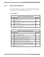
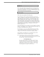
Table 10.1-7
Test Equipment
2500-type, single line touchtone phones, one with a message waiting indicator.
Terminal/teleprinter directly connected to VP 300 Port J1 or SP1 via RS-232C cable.
Hard copy of the VP 300 configuration database.
Hard copy of the PBX configuration.
Single line analog extensions, connected to RJ11 jacks for testing.
Individually addressable trunk line into the PBX.
Mitel Superset 4 display phone. This phone is required for testing purposes only.
It is used to emulate the MIC board.
Modular adapters for 2500-type and Superset 4 extensions. Armiger AA2560A or
equivalent are recommended.
Description
Quantity
2
1
1
1
2
1
1
2
Summary of Contents for VP 300
Page 2: ......
Page 10: ......
Page 14: ......
Page 20: ...Toshiba VP Systems Release 7 1 July 1994 ...
Page 52: ...Toshiba VP Systems Release 6 1 February 1993 2 14 Installation and Maintenance Manual ...
Page 56: ...Toshiba VP Systems Release 7 1 July 1994 ...
Page 146: ......
Page 312: ...Toshiba VP Systems Release 7 1 July 1994 ...
Page 314: ......
Page 444: ......
Page 496: ......
Page 542: ......
Page 598: ...Toshiba VP Systems Release 6 1 February 1993 ...
Page 600: ...Toshiba VP Systems Release 6 1 February 1993 ...


