7.
Tighten the 18 screws on the top and bottom of the MBA and the 5 screws
on the MBA I/O panel.
8.
Plug the fan tray harness into the top disk drive backplane.
9.
Connect the two flat cables from the top disk drive backplane to the MBA.
10. Connect the disk drive backplane power harness to the MBA.
11. Connect the maintenance port cable to the connector on the top left corner of
the MBA.
12. Install the power filter assembly as described in the Power Filter Assembly
section in this chapter.
13. Bolt on the bottom rear panel with four screws, and reconnect the cables as
they were connected on the old MBA.
14. Bolt on the top rear panel with four screws.
15. Verify that the power supply unit is in the OFF position. Attach the power
cord.
If the cabinet is DC powered, reconnect the wires from the DC power
source to the PFA.
16. Plug the remaining boards into the cabinet.
17. Tighten the two fasteners on the front of the power supply unit.
18. Test the system for proper operation by following the procedures in the
INSTALLATION chapter in this manual.
19. Close and lock the door to the cabinet.
■
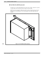
Disk Drive Backplane (DDB)
The disk drive backplanes provide communication and DC power buses from the Motherboard to the
disk drive assembly. There are two DDBs, one for Shelf B and one for Shelf C.
Toshiba VP Systems Release 7.1
July, 1994
MAINTENANCE
5-89
Summary of Contents for VP 300
Page 2: ......
Page 10: ......
Page 14: ......
Page 20: ...Toshiba VP Systems Release 7 1 July 1994 ...
Page 52: ...Toshiba VP Systems Release 6 1 February 1993 2 14 Installation and Maintenance Manual ...
Page 56: ...Toshiba VP Systems Release 7 1 July 1994 ...
Page 146: ......
Page 312: ...Toshiba VP Systems Release 7 1 July 1994 ...
Page 314: ......
Page 444: ......
Page 496: ......
Page 542: ......
Page 598: ...Toshiba VP Systems Release 6 1 February 1993 ...
Page 600: ...Toshiba VP Systems Release 6 1 February 1993 ...

