E.
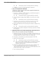
Press the SEND MSG softkey. Is phone B message waiting indicator on?
NO
➧
Determine the cause and correct the problem before continuing.
F.
Dial the extension number of phone B again. Does softkey 4 of the Superset 4 have the
SEND MSG prompt and softkey 5 have the CANCEL prompt?
NO
➧
Determine the cause and correct the problem before continuing.
G. Press the CANCEL softkey. Is phone B’s message waiting indicator OFF?
NO
➧
Determine the cause and correct the problem before continuing.
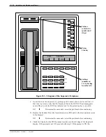
H. Press the EXIT softkey on the Superset 4. The time and date should return to the
superset display.
I.
Hang up the Superset 4. Using phone A, call the Superset 4. Does the PBX return
reorder tone? If not, check that the COS for MWI has Option 235, ORIGINATE
ONLY, enabled. Correct the problem before continuing.
J.
Hang up phone A.
8.
CALLS TO THE INTERCEPT EXTENSION (ATTENDANT)
(For new installation only)
This test verifies that each VP 300 port extension can transfer a call to the intercept
extension (attendant).
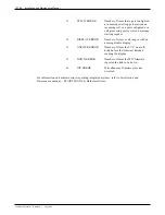
A. Connect the Superset 4 phone to the PBX extension used for the first MIC port.
B. Wait for the PBX to initialize the Superset 4. This may take as long as 30 seconds.
Once the set is initialized, the display should show the time and date. If the display
does not show the time and date within 30 seconds of connecting the phone, correct the
problem before continuing. If the display contains information other than the time and
date, lifting the Superset handset off-hook and replacing it may correct the problem.
C. From phone A, call the extension number of the Superset.
D. Answer the Superset by pressing the speaker on/off button. Transfer phone A to the
attendant by pressing the TRANS/CONF softkey, dialing
0
, and pressing the HANG
UP softkey. Does phone A get connected to the attendant?
NO
➧
Determine the cause and correct the problem before continuing.
E.
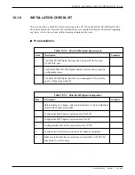
Connect the Superset to the RJ11 jack of the next MIC port extension and make sure
the phone initializes and displays the time and date. Repeat steps B through D for each
MIC port until every MIC port has successfully transferred a call to the attendant.
The PBX testing is now complete. Proceed with installation of the MIC board(s). Do not
connect any line cords to the VP 300 until after all MIC boards are installed.
Toshiba VP Systems
Release 7.1
July, 1994
10.1-32
Installation and Maintenance Manual
Summary of Contents for VP 300
Page 2: ......
Page 10: ......
Page 14: ......
Page 20: ...Toshiba VP Systems Release 7 1 July 1994 ...
Page 52: ...Toshiba VP Systems Release 6 1 February 1993 2 14 Installation and Maintenance Manual ...
Page 56: ...Toshiba VP Systems Release 7 1 July 1994 ...
Page 146: ......
Page 312: ...Toshiba VP Systems Release 7 1 July 1994 ...
Page 314: ......
Page 444: ......
Page 496: ......
Page 542: ......
Page 598: ...Toshiba VP Systems Release 6 1 February 1993 ...
Page 600: ...Toshiba VP Systems Release 6 1 February 1993 ...


