3
INSTALLATION
Toshiba VP Systems Release 7.1 July, 1994
Figures and Tables
Figure
Description
Page
3-1
VP 300 Floor Plan for Domestic Installation......................................................................................
3-4
3-1.1
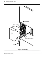
VP 300 DC Cover..............................................................................................................................
3-8
3-2
Field Wiring for –48 VDC Powered VP 300 ......................................................................................
3-9
3-3
First and Second RS-232C Serial Port Cable Pin-outs for Connection
to Terminal Equipment (DTE) ........................................................................................................... 3-12
3-4
VP 300 to External Modem Pin-outs ................................................................................................. 3-13
3-5
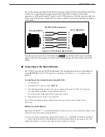
Connecting to VP 300’s Internal Modem........................................................................................... 3-14
3-6
VP 300 Cabinet Installed in 19" Rack ............................................................................................... 3-25
3-7
Typical VP 300 Connections ............................................................................................................. 3-31
3-8
Connector Block ................................................................................................................................ 3-33
3-9
Cabinet to Block Connection ............................................................................................................. 3-34
Table
Description
Page
3-1
Input Circuit Current Capacity ...........................................................................................................
3-5
3-2
Input Power Requirements................................................................................................................
3-6
3-3
Equipment Provided by Distributor....................................................................................................
3-9
3-4
DCE Pin-outs for RS-232C Terminal to VP 300 Cable Connections ................................................ 3-11
3-5
External Modem Pin-outs .................................................................................................................. 3-12
3-6
Power Supply Output Rating and Acceptable Operating Ranges ..................................................... 3-23
3-7
DAC Installation Kit Part #740-6045-001 .......................................................................................... 3-32
3-8
66M4-4W Connector Block Designators ........................................................................................... 3-35
3-9
Testing Equipment ............................................................................................................................ 3-36
Summary of Contents for VP 300
Page 2: ......
Page 10: ......
Page 14: ......
Page 20: ...Toshiba VP Systems Release 7 1 July 1994 ...
Page 52: ...Toshiba VP Systems Release 6 1 February 1993 2 14 Installation and Maintenance Manual ...
Page 56: ...Toshiba VP Systems Release 7 1 July 1994 ...
Page 146: ......
Page 312: ...Toshiba VP Systems Release 7 1 July 1994 ...
Page 314: ......
Page 444: ......
Page 496: ......
Page 542: ......
Page 598: ...Toshiba VP Systems Release 6 1 February 1993 ...
Page 600: ...Toshiba VP Systems Release 6 1 February 1993 ...

