•
Define a slot using the SLOTS Table.
Use the instructions below to ADD or MODIFY a slot.
Configure the SLOTS Table to reflect the DAC. Table 11-1 lists the information required
for each port. The left column contains the information required by the VP 300. The right
column contains the possible responses.
The VP 300 recognizes that the DAC can only work in a Direct Access (DX) mode.
Therefore, when adding or modifying a port, it automatically assumes this mode. In
addition, port outcalling and channel testing are automatically set to NO when adding or
modifying a port for DAC.
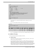
The following is an example of using the UPDATE program to ADD a slot to the SLOTS
Table. If you are modifying a slot to accept the DAC, use the MODIFY command.
Toshiba VP Systems
Release 6.1
February, 1993
11-6
Installation and Maintenance Manual
Table 11-1 SLOTS Table Configuration Changes
Information Required
Possible Responses
Connected to the port (1-8 digits). For DX
ports this may be any 1-8 digit reference
number or NONE.
The COS should be unique for DX ports.
Since DX mode is already assumed, enter the
appropriate choice for the installation.
Since DX mode is already assumed, enter the
appropriate choice for the installation.
(Wink, Immediate, and Delay are used for
DID trunks; Loop and Ground are used for
PBX trunks.)
Extension Number
Class of Service (COS) (0-255)
What type of signaling (DTMF or
Rotary)?
Trunk Type (Wink, Immediate, Delay?)
(Loop or Ground?)
Summary of Contents for VP 300
Page 2: ......
Page 10: ......
Page 14: ......
Page 20: ...Toshiba VP Systems Release 7 1 July 1994 ...
Page 52: ...Toshiba VP Systems Release 6 1 February 1993 2 14 Installation and Maintenance Manual ...
Page 56: ...Toshiba VP Systems Release 7 1 July 1994 ...
Page 146: ......
Page 312: ...Toshiba VP Systems Release 7 1 July 1994 ...
Page 314: ......
Page 444: ......
Page 496: ......
Page 542: ......
Page 598: ...Toshiba VP Systems Release 6 1 February 1993 ...
Page 600: ...Toshiba VP Systems Release 6 1 February 1993 ...


