■
Configuration of Test Extensions
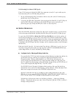
Configure two additional analog extensions in the Mitel SX-2000 before performing the tests
described in the following sections. The configuration procedure for these extensions follows.
1.
Allocate two analog extensions (2500-type single line) in the PBX. The extension numbers
of these extensions must be consistent with the format of the mailbox numbers in the
VP 300 USER Table. For example, the first digit and number of digits in the extensions
must correspond to the mailbox numbering scheme.
2.
Configure the analog extensions so that they have a PBX class of service with the Call
Forward No Answer Timer set to 20 seconds and Call Forwarding (Internal Destination)
enabled. If this installation is using the VP 300 to control message waiting indicators, make
sure the analog extension with a message waiting indicator is assigned an ONS/OPS Circuit
Descriptor that enables the indicator. Check that the interconnect number for both
extensions permits them to access the VP 300 hunt group. Make sure that neither extension
is assigned a name in the telephone directory form.
3.
Assign one of the analog extension Call Rerouting as follows: The First Alternative answer
point is the first MIC port in the VP 300 hunt group, for all types of calling devices, on
both Busy/DND and No Answer. The Second Alternative answer point is the second analog
extension, for all types of calling devices. Set up a Call Rerouting Always Alternative that
reroutes to the first MIC port in the VP 300 hunt group for all types of calling devices, but
do not assign this Always Alternative to either analog extension yet. Instead, assign an
Always Alternative number that results in No Reroute for Day, Night 1, and Night 2
operation.
4.
Allocate one trunk line that can be individually called into the PBX. This is used to test
external calls into the VP 300. Configure this trunk to ring directly into the extension
number of the MIC port hunt group. During the testing, the trunk is reconfigured to ring
directly into one of the analog test extensions. Change the Trunk Label entry on this
trunk’s Trunk Service Assignment form to be T999 TEST.
■
Mitel SX-2000 Testing
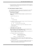
Perform the tests in this section before the actual installation of the MIC board. Disconnect all
cables connecting the VP 300 ports to the Mitel SX-2000 for these tests.
This section refers to the parts of the Superset 4 telephone according to the following diagram,
Figure 10.3-5. Refer to this diagram for the locations of parts of the Superset 4.
Toshiba VP Systems
Release 6.1
February, 1993
MITEL SX-2000 ADAPTIVE INTEGRATION
10.3-27
Summary of Contents for VP 300
Page 2: ......
Page 10: ......
Page 14: ......
Page 20: ...Toshiba VP Systems Release 7 1 July 1994 ...
Page 52: ...Toshiba VP Systems Release 6 1 February 1993 2 14 Installation and Maintenance Manual ...
Page 56: ...Toshiba VP Systems Release 7 1 July 1994 ...
Page 146: ......
Page 312: ...Toshiba VP Systems Release 7 1 July 1994 ...
Page 314: ......
Page 444: ......
Page 496: ......
Page 542: ......
Page 598: ...Toshiba VP Systems Release 6 1 February 1993 ...
Page 600: ...Toshiba VP Systems Release 6 1 February 1993 ...


