For proper operation, DTR (pin 20) must be exerted TRUE by the terminal. RTS (pin 4) must be
exerted TRUE by the terminal when the terminal is able to accept data, or be left unconnected.
Terminal/teleprinter equipment having pins 1 and 7 connected together may cause intermittent
problems with the VP 300. Terminal/teleprinters requiring Data Set Ready (DSR) may require
connecting pins 6 and 8 together, or 8 and 20 together at the terminal end of the RS-232C cable. If you
have a problem or question with your terminal/teleprinter, call Toshiba.
■
Connecting an External Modem to the VP 300
An external modem may be used if a dedicated modem connection is required, or if a modem of baud
rate different from the VP 300 internal modem is required. A modem that supports standard baud rate
(300 to 9600 baud) may be connected to the VP 300 System Terminal Port.
Table 3-5
External Modem Pin-outs
Modem
Pin Number
VP 300
Pin Number
Modem Signal
Name/Function
VP 300
Name/Function
2
3
5
4
7
8
20
3
2
4
5
7
20
8
Transmit Data
Receive Data
CTS
RTS
Signal Ground
DCD
DTR
Receive Data
Transmit Data
RTS
CTS
Signal Ground
DTR
DCD
To Terminal (DTE)
VP 300 (DCE)
Protection Ground
TX
RX
RTS
CTS
Signal Ground
DCD
DTR
1
2
3
4
5
7
8
20
1
2
3
4
5
7
8
20
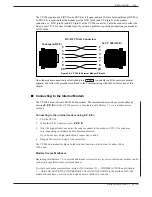
Figure 3-3 First and Second RS-232C Serial Port Cable Pin-outs
for Connection to Terminal Equipment (DTE)
Toshiba VP Systems Release 7.1 July, 1994
3-12
Installation and Maintenance Manual
Summary of Contents for VP 300
Page 2: ......
Page 10: ......
Page 14: ......
Page 20: ...Toshiba VP Systems Release 7 1 July 1994 ...
Page 52: ...Toshiba VP Systems Release 6 1 February 1993 2 14 Installation and Maintenance Manual ...
Page 56: ...Toshiba VP Systems Release 7 1 July 1994 ...
Page 146: ......
Page 312: ...Toshiba VP Systems Release 7 1 July 1994 ...
Page 314: ......
Page 444: ......
Page 496: ......
Page 542: ......
Page 598: ...Toshiba VP Systems Release 6 1 February 1993 ...
Page 600: ...Toshiba VP Systems Release 6 1 February 1993 ...


