■
Power Up the System
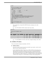
Turn ON the -48 VDC telephony power supply(s). Verify that the green LED is lit on the
DAC I/O panel.
☞
The green LED on each DAC is used to indicate that the card passed selftest
diagnostics.
If the LED on the DAC I/O panel is not lit, remove the power connector from the DAC I/O
panel and use a voltmeter to verify that the -48 VDC is present and has the correct polarity
on the connector.
If the voltage does not appear on the connector, either the power cable or power supply is
bad, or AC power is not applied to the power supply.
If the voltage does appear on the connector, the DAC I/O panel is bad.
■
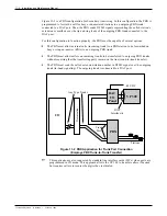
Testing the Trunks
Once power is confirmed, complete the following:
1.
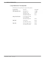
Connect a test set (with proper dialing type — DTMF or rotary) to each port’s tip and
ring wires at the demarcation point.
2.
Verify the battery polarity: -48 VDC on the ring side of the line.
3.
Go off-hook to place a call. Dial a valid mailbox number to test the DAC for proper
operation. This verifies the trunk wiring and DAC operation before connecting the CO
side to the DAC.
4.
Connect (wire) the tip and ring of the DAC to the tip and ring of the DID trunk at the
demarcation point.
5.
Have the CO enable the trunks.
6.
Place test calls to verify proper operation for all trunks.
It is extremely important for the polarity to be correct. For DID trunks, have
the CO verify that:
• The battery is on the ring side of the line.
• The ground is on the tip side of the line.
When the polarity is looked at from the CO test desk, it is the battery and
ground supplied through the DAC that is looked at. If the CO test desk
determines that the battery and ground are reversed, correct the wiring
between the demarcation point and the DAC I/O panel.
W A R N I N G
Toshiba VP Systems
Release 6.1
February, 1993
DAC INSTALLATION
11-13
Summary of Contents for VP 300
Page 2: ......
Page 10: ......
Page 14: ......
Page 20: ...Toshiba VP Systems Release 7 1 July 1994 ...
Page 52: ...Toshiba VP Systems Release 6 1 February 1993 2 14 Installation and Maintenance Manual ...
Page 56: ...Toshiba VP Systems Release 7 1 July 1994 ...
Page 146: ......
Page 312: ...Toshiba VP Systems Release 7 1 July 1994 ...
Page 314: ......
Page 444: ......
Page 496: ......
Page 542: ......
Page 598: ...Toshiba VP Systems Release 6 1 February 1993 ...
Page 600: ...Toshiba VP Systems Release 6 1 February 1993 ...


