


User Manual
194 of 562
V 1.0
2021-08-25
XDPP1100 technical reference manual
Digital power controller
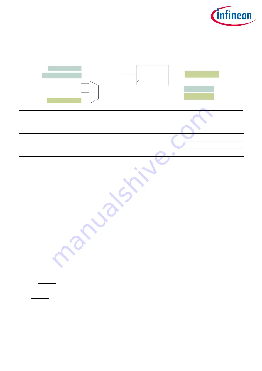
Telemetry
•
ISEN and BISEN, which can be selected individually to provide I
IN
, or input CE (
) is provided to
estimate I
IN
based on measured V
IN
, V
OUT
, I
OUT
and duty cycle if I
IN
is not directly sensed
•
Register
tlmX_iin_src_sel
, which allows the selection of the I
IN
input source according to
Figure 68
I
IN
telemetry block diagram
Table 54
I
IN
telemetry source selection
tlm_iin_src_sel
Source
0
ISEN
1
BISEN
2
Estimated I
IN
3
Estimated I
IN
The selected input source is low-pass filtered at a programmable BW determined by register
tlmX_kfp_iin
. The
BW programming is shown in
. The output of the LPF is available as read-only register
tlmX_iin_lpf
. It
is used for the READ_IIN PMBus command as well as the I
IN
fault functions.
8.5
Input CE
The I
IN
submodule is shown in
. The estimated input current is obtained according to Equation (8.1).
𝐼
𝐼𝑁
= 𝐼
𝑂𝑈𝑇
∗ [
𝑉
𝑂𝑈𝑇
𝑉
𝐼𝑁
+ 𝑎𝑙𝑝ℎ𝑎 ∗ (𝑁𝑥 ∗ 𝐷𝑢𝑡𝑦 −
𝑉
𝑂𝑈𝑇
𝑉
𝐼𝑁
)]
(8.1)
Where:
•
Nx is defined according to Equation (8.2) in case of HB topology and according to Equation (8.3) for other
topologies
•
Alpha is defined via register
tlmX_iin_est_alpha
, and this value is used to fine-tune the estimate shifting of
the relative percentage of V
OUT
/V
IN
versus duty cycle used to estimate I
IN
from I
OUT
𝑁𝑥 = 2 ∗
𝑁𝑡𝑢𝑟𝑛_𝑠𝑒𝑐
𝑁𝑡𝑢𝑟𝑛_𝑝𝑟𝑖
(8.2)
𝑁𝑥 =
𝑁𝑡𝑢𝑟𝑛_𝑠𝑒𝑐
𝑁𝑡𝑢𝑟𝑛_𝑝𝑟𝑖
(8.3)
Register
tlmX_transformer_scale_loop
defines Nx and is automatically computed by FW based on PMBus
command MFR_TRANSFORMER_SCALE and the selected topology.
tlmX_kfp_iin[5:0]
isp1_iin_cavg[12:0]
U6.7
LPF
F
SWITCH
0
1
2-3
isp2_iin_cavg[12:0]
U6.7
U6.7
tlmX_iin_est[12:0]
tlmX_iin_src_sel[2:0]
tlmX_iin_lpf[12:0]
U6.7
RW parameters
RO parameters


