


User Manual
142 of 562
V 1.0
2021-08-25
XDPP1100 technical reference manual
Digital power controller
Digital pulse width modulator
It should be noted that for DE modulation (if the pulse on and off times allow), it is possible to use interrupts on
t1 and t2 (see
) in order to change
rampX_force_duty
between edges.
7.4
Burst mode
BM is a light-load operating state that is only supported in bridge topologies. During this state, the controller
provides a burst of PWM pulses upon the error voltage dropping below a programmed threshold. The BM is
enabled by setting PMBus command POWER_MODE = 0 and disabled by setting POWER_MODE = 3.
The BM is entered when the output current falls below the level defined by the register
pid_burst_mode_ithr
,
which is computed according to Equation (7.10).
𝑝𝑖𝑑_𝑏𝑢𝑟𝑠𝑡_𝑚𝑜𝑑𝑒_𝑖𝑡ℎ𝑟 =
2∗𝐼𝑜𝑢𝑡_𝑏𝑢𝑟𝑠𝑡_𝑒𝑛𝑡𝑟𝑦_𝑡ℎ𝑟𝑒𝑠ℎ𝑜𝑙𝑑
𝑀𝐹𝑅_𝐼𝑂𝑈𝑇_𝐴𝑃𝐶
(7.10)
Where Iout_burst_entry_threshold is the output current value in amps at which to enter the BM and
MFR_IOUT_APC is the PMBus command defining the APC setting of the IADC. BM entry and operation are
illustrated in
Figure 62
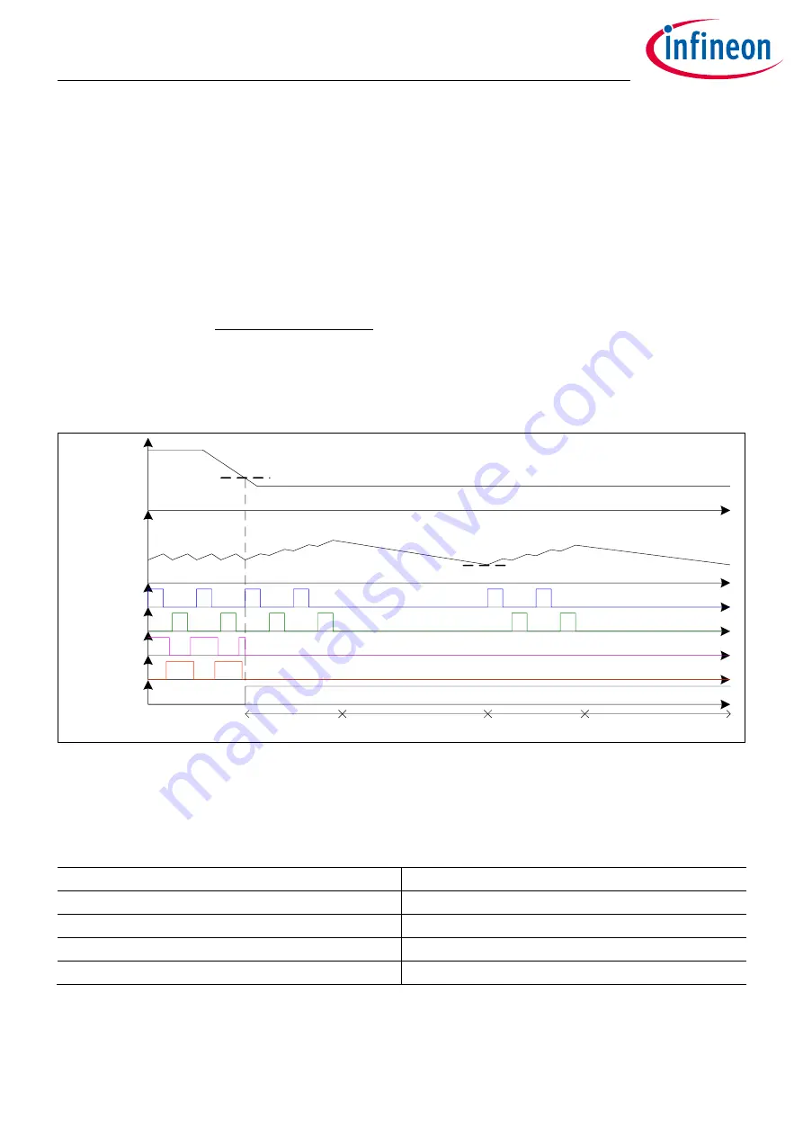
BM operation with pid_burst_reps = 1
Upon entering BM, the XDPP1100 disables the SR FETs and outputs a burst of PWM pulses on each half-cycle
corresponding to a number programmed via register
pid_burst_reps
as defined in
Table 44
Burst count programming at BM
pid_burst_reps
Number of PWM pulses per burst
0
1
1
2
2
4
3
8
Subsequent to the initial burst, the PWM outputs are disabled until the output voltage drop produces an error
voltage greater than the value defined in register
pid_burst_mode_err_thr
. This parameter is computed
according to Equation (7.11).
I
OUT
VSEN
PWM1
SR1
PWM2
SR2
pid_burst_mode_ith
pid_burst_mode_err_thr
Burst Mode
burst ON time
burst OFF time
burst ON time
burst OFF time


