Chapter 11 Motion Control Instructions
11-127
11
position is converted from the number of pulses the external encoder port of the controller
receives through axis parameters.
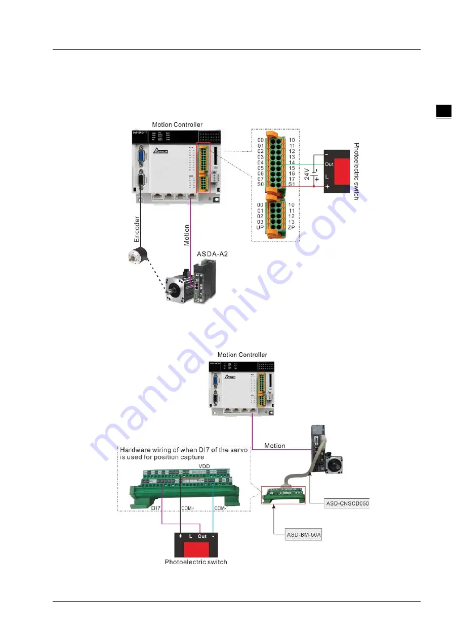
Mode 1: The external signal triggers I point of the motion controller and the position capture is
conducted through the falling edge of the input point specified by
TriggerInput
. The captured
position is converted from the number of pulses the external encoder port of the controller
receives through axis parameters.
Mode 2
The external signal triggers the high-speed input point: DI7 of the servo drive. The position captured is
converted from the number of pulses which the servo motor feeds back to the servo drive through axis
parameters.
Summary of Contents for DVP-15MC Series
Page 19: ...DVP 15MC Series Motion Controller Operation Manual 1 4 _1 MEMO...
Page 23: ...DVP 15MC Series Operation Manual 2 4 _2 MEMO...
Page 31: ...DVP 15MC Series Motion Controller Operation Manual 3 8 _3 MEMO...
Page 75: ...DVP 15MC Series Motion Controller Operation Manual 6 26 _6 MEMO...
Page 87: ...DVP 15MC Series Motion Controller Operation Manual 7 12 _7 MEMO...
Page 432: ...Chapter 8 Logic Instructions 8 345 8_ MEMO...
Page 470: ...DVP 15MC Series Motion Controller Operation Manual 10 34 10 MEMO...
Page 878: ...DVP 15MC Series Motion Controller Operation Manual 11 408 11 1 MEMO...
Page 920: ...DVP 15MC Series Motion Controller Operation Manual A 16 A MEMO...
Page 941: ...D 1 D Explanation of Homing Modes Table of Contents D 1 Explanation of Homing Modes D 2...
Page 966: ...DVP 15MC Series Motion Controller Operation Manual D 26 D MEMO...


