Power Assisted Steering System: 6C-43
5) Turn ON ignition switch without engine running and
select scan tool “Data List” mode due to checking
“Sensor (Main) Torque” and “Sensor (Sub) Torque”
displayed on scan tool when steering wheel turned
left and right (if used).
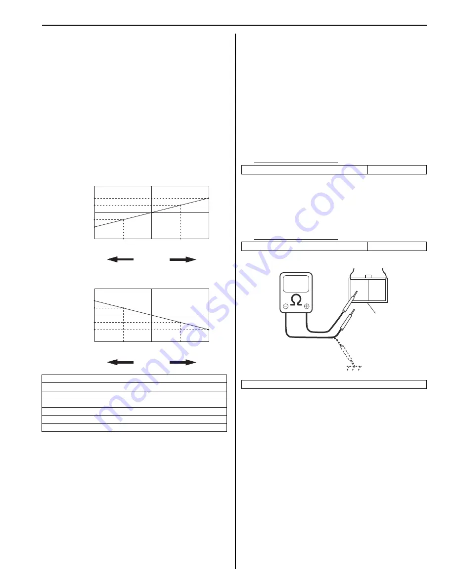
6) Check that characteristic of torque sensor (main and
sub) output voltage or scan tool data and steering
force is as following graph when steering wheel is
turned left and right. If sensor voltage or scan tool
data is out of specified value or does not vary linearly
as the following graph, check EPS control module
and its circuit referring to “Inspection of P/S Control
Module and Its Circuits”.
If they are OK, replace steering gear case assembly.
P/S Motor and Its Circuit Inspection
S6RW0C6306013
1) Check motor circuit referring to Step 2 to 3 of “DTC
C1141 / C1142 / C1143 / C1145: Motor Circuit
Failure”. If check result is not satisfactory, repair
motor circuit.
2) Disconnect motor connector from steering gear case
assembly with ignition switch turned OFF.
3) Check for resistance between terminals of motor
connector.
If check result is not as specified, check P/S motor
harness for continuity. If it is OK, replace steering
gear case assembly.
Motor circuit resistance
4) Check for insulation between each terminal of motor
connector and body ground.
If check result is not as specified, check P/S motor
harness for insulation. If it is OK, replace steering
gear case assembly.
Motor circuit resistance
[A]: Main sensor
[B]: Sub sensor
[C]: Steering force at left turn
[D]: Steering force at right turn
[E]: Steering wheel at free
[F]: “Sensor (Main) Torque” in “Data List” displayed on scan tool
[G]: “Sensor (Sub) Torque” in “Data List” displayed on scan tool
0
[E]
[N.m]
MAX
MAX
[D]
[C]
[E]
[D]
[C]
2.33 - 2.68
[V]
[F]
[G]
[A]
[B]
6
6
1.65 - 1.9
(1.0 - 1.3)
3.0 - 3.4
(3.7 - 4.0)
0
5
2.33 - 2.68
1.65 - 1.9
(1.0 - 1.3)
3.0 - 3.4
(3.7 - 4.0)
0
5
0
[N.m]
MAX
MAX
[V]
6
11.76
11.76
11.76
11.76
6
0
11.5
-12.0
0
-12.0
11.5
I7RW01632011-02
“E12-1” and “E12-2” (For motor)
Approx. 1
Ω
Each terminal and body ground
No continuity
[A]: Motor connector “E12” (viewed from harness side)
1
2
[A]
I6RW0C630012-02
Summary of Contents for 2006 SX4
Page 2: ......
Page 6: ......
Page 22: ...00 15 Precautions...
Page 38: ...0B 7 Maintenance and Lubrication...
Page 378: ...1K 6 Exhaust System...
Page 848: ...6C 46 Power Assisted Steering System...
Page 954: ...7B 89 Air Conditioning System Automatic Type...
Page 1086: ...8B 121 Air Bag System...
Page 1381: ...Paint Coatings 9L 7 I5RW0C9C0005 01 A Apply sealant 1 Hole...
Page 1382: ...9L 8 Paint Coatings I5RW0C9C0006 01 A Apply sealant covering flange end...
Page 1476: ...Prepared by 1st Ed Feb 2007...


