TONE-BD (Tone-Clock Circuit)
Issue 1 May 2002
8-1669
555-233-143
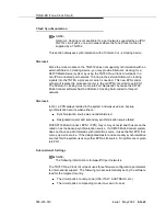
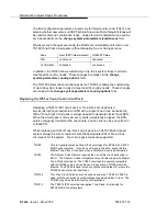
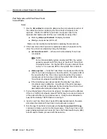
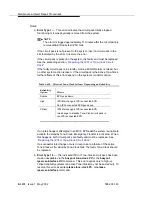
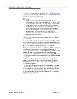
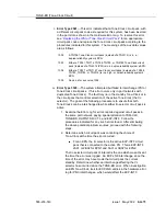
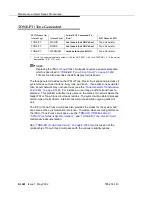
To verify that the new Tone-Clock circuit pack can generate clocks for the
system, switch to the new Tone-Clock with set tone-clock UUC override,
and execute test tone-clock UUC. If the new Tone-Clock circuit pack is
able to generate system clocks, there will be no system disruption.
!
CAUTION:
If the new Tone-Clock circuit pack is not able to generate system
clocks, this procedure becomes destructive. The system will detect a
loss of clock and recover accordingly. If the Tone-Clock circuit pack
being replaced is in an EPN, the system will reset the EPN (EPN cold
restart). After either type of restart, the faulty Tone-Clock circuit pack
will be in standby mode.
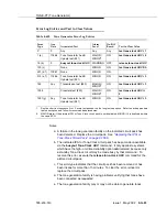
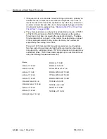
6. Place several phone calls.
7. After repairs in an EPN, the set tone-clock UUC command should be used
if required to make the preferred Tone-Clock circuit pack active.
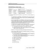
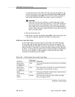
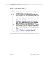
IPSI/Tone Clock LED States
For the TN2312 IPSI circuit pack, there are four LEDs on the IPSI’s faceplate.
The top three LEDs are the standard ones found on any TN circuit pack. The
fourth LED imitates the TN2182B Tone-Clock’s amber LED. The active/standby
state of an IPSI or Tone-Clock circuit pack may also be determined by looking at
its LEDs. A continuously lit red LED on the circuit pack indicates a reported fault
on one or more of its MOs. Flashing patterns of the yellow and green LEDs
correspond to the following service states:
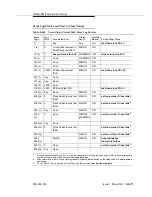
Table 8-647.
LED Condition/Tone-Clock Circuit States
Condition
Tone-Clock
Circuit State Explanation
flashing yellow
2.7 seconds on
0.3 seconds off
active
An external timing source is being used as a synchronization
reference
1
.
flashing yellow
0.3 seconds on
2.7 seconds off
active
The local oscillator on the IPSI or Tone-Clock circuit pack is
being used as a synchronization reference.
yellow
on continuously
active
The circuit pack has been reset but has not been told which
synchronization source to use.
yellow
LED off
standby
The circuit pack is in standby mode, (neither generating
tones nor supplying clocks).
Continued on the next page
Summary of Contents for S8700 Series
Page 50: ...Maintenance Architecture 555 233 143 1 26 Issue 1 May 2002 ...
Page 74: ...Initialization and Recovery 555 233 143 3 12 Issue 1 May 2002 ...
Page 186: ...Alarms Errors and Troubleshooting 555 233 143 4 112 Issue 1 May 2002 ...
Page 232: ...Additional Maintenance Procedures 555 233 143 5 46 Issue 1 May 2002 ...
Page 635: ...status psa Issue 1 May 2002 7 379 555 233 143 status psa See status tti on page 7 406 ...
Page 722: ...Maintenance Commands 555 233 143 7 466 Issue 1 May 2002 ...

