


UDS1-BD (UDS1 Interface Circuit Pack)
Issue 1 May 2002
8-1745
555-233-143
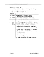
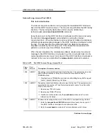
1302
FAIL
Attempting to use the 120A1 CSU module with a UDS1 circuit pack that is
configured for 32-channel (2.048-Mbps) operation. The CSU module only
works with a DS1 board configured for 24-channel (1.544-Mbps) operation in
the United States of America.
1. If the 120A1 CSU module is to be used, physically remove the UDS1 circuit
pack and reconfigure for 24-channel (1.544-Mbps) operation.
2. Reinsert the circuit pack and run the test again.
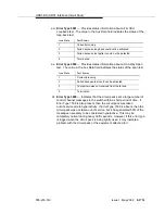
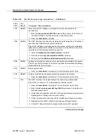
1303
FAIL
The DS1 circuit pack Suffix is incorrect for CSU module/T1 sync splitter or E1
Sync Splitter administration.
The DS1 circuit pack Suffix is incorrect for CSU module/T1 sync splitter
administration. The
Near-End CSU Type
field on the add ds1 form has
been administered as
integrated
but the DS1 circuit pack is not a TN464F
or later suffix UDS1 board.
1. If the CSU module/T1 sync splitter is to be used, and the
Near-End CSU
Type
field is set to
integrated
to allow for CSU module/T1 sync
splitter administration, remove the circuit pack and replace it with a TN464F
or later suffix board. Otherwise, use the change ds1 command to change
the
Near-End CSU Type
field to
other
.
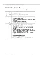
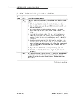
The DS1 circuit pack Suffix is incorrect for E1 Sync Splitter administration. The
E1 Sync-Splitter?
field on the add ds1 form has been administered as
y
but the DS1 circuit pack is not a TN464F or later suffix UDS1 board.
1. If the E1 Sync Splitter is to be used, and the
E1 Sync-Splitter?
field
is set to
y
to allow for E1SS administration, remove the circuit pack and
replace it with a TN464F
or later suffix board. Otherwise, use the change
ds1 command to change the
E1 Sync-Splitter?
field to
n
.
1310
FAIL
The DS1 Board Loopback (BLB) demand test (#1209) failed.
1. Repeat the test using the test ds1-loop UUCSS ds1/csu-loopback-tests
command.
2. If the BLB test continues to fail, then replace the UDS1-BD circuit pack.
3. Run this test again.
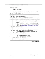
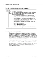
Table 8-673.
Test #138 Loss of Signal Alarm Inquiry Test —
Continued
Error
Code
Test
Result
Description / Recommendation
Continued on next page
Summary of Contents for S8700 Series
Page 50: ...Maintenance Architecture 555 233 143 1 26 Issue 1 May 2002 ...
Page 74: ...Initialization and Recovery 555 233 143 3 12 Issue 1 May 2002 ...
Page 186: ...Alarms Errors and Troubleshooting 555 233 143 4 112 Issue 1 May 2002 ...
Page 232: ...Additional Maintenance Procedures 555 233 143 5 46 Issue 1 May 2002 ...
Page 635: ...status psa Issue 1 May 2002 7 379 555 233 143 status psa See status tti on page 7 406 ...
Page 722: ...Maintenance Commands 555 233 143 7 466 Issue 1 May 2002 ...


