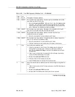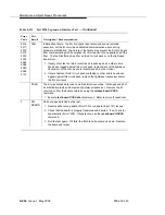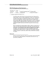
EXP-INTF (Expansion Interface Circuit Pack)
Issue 1 May 2002
8-819
555-233-143
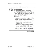
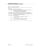
5001
FAIL
Initialization failure: the EI circuit pack reset successfully and restarted
execution, but the EI circuit pack could not synchronize itself during hardware
initialization.
1. Issue the reset board PCSS command. If the circuit pack is in the active
link, this procedure can be very destructive. If a test board PCSS shows
every test passing, and there is no standby link to which you can switch,
perform this reset at a time when service is least disrupted by losing use of
the PN.
2. If the reset fails with the same error code, execute the test tone-clock PC
command where P is the network that contains this EI circuit pack and C is
the carrier that contains the active Tone-Clock on network P. Also look for
SYNC and TONE-BD errors. Resolve any SYNC and TONE-BD errors by
following the Maintenance documentation for these MOs. Then reissue
the reset board PCSS command.
3. If the EI circuit pack still fails to reset with the same error code, replace the
EI circuit pack.
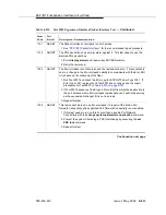
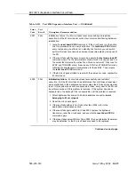
5002
FAIL
Initialization failure: EI circuit pack reset successfully and restarted
execution. But the EI circuit pack has determined that a lightwave transceiver
was not attached to the backplane connector when the EI circuit pack was last
reset. If this system does not have duplicate EI links, every user in the PN will
be without service until this problem is resolved. If this system does have
duplicate links, the backup EI link is unavailable until this problem is resolved.
1. Attach lightwave transceiver to 25-pair backplane connector in slot
belonging to EI circuit pack.
2. Reset the circuit pack again.
3. If the reset fails with an Error Code other than 5002, refer to the
appropriate maintenance section.
4. If the reset fails again with Error Code 5002, replace the lightwave
transceiver, reset the circuit pack, and execute the reset board PCSS
command again.
5. If the reset fails again with Error Code 5002, the new lightwave transceiver
may be defective, or the EI circuit pack may need to be replaced.
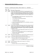
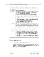
Table 8-311.
Test #224 Expansion Interface Test —
Continued
Error
Code
Test
Result
Description / Recommendation
Continued on next page
Summary of Contents for S8700 Series
Page 50: ...Maintenance Architecture 555 233 143 1 26 Issue 1 May 2002 ...
Page 74: ...Initialization and Recovery 555 233 143 3 12 Issue 1 May 2002 ...
Page 186: ...Alarms Errors and Troubleshooting 555 233 143 4 112 Issue 1 May 2002 ...
Page 232: ...Additional Maintenance Procedures 555 233 143 5 46 Issue 1 May 2002 ...
Page 635: ...status psa Issue 1 May 2002 7 379 555 233 143 status psa See status tti on page 7 406 ...
Page 722: ...Maintenance Commands 555 233 143 7 466 Issue 1 May 2002 ...

