


Pos: 2 /Dokumentation allgemein/Einband/Einband Handbuch - Frontseite 2017 - mit DocVariablen (Standard) @ 28\mod_1486477502910_0.docx @ 405388 @ @ 1
Manual
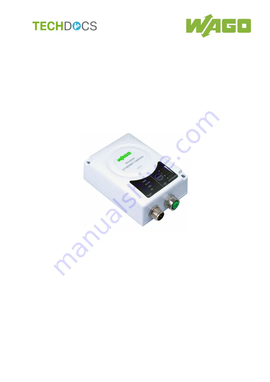
WAGO-I/O-SYSTEM 758
758-918
Wireless ETHERNET Gateway
Wireless Transmission Link
for ETHERNET Protocols
Version 1.0.2
Pos: 3 /Alle Serien (Allgemeine Module)/Rechtliches, Allgemeines/Impressum für Standardhandbücher - allg. Angaben, Anschriften, Telefonnummern und E-Mail-Adressen @ 3\mod_1219151118203_21.docx @ 21060 @ @ 1


