


Circuit Pack LEDs
Issue 1 May 2002
6-11
555-233-143
DS1 Facility LEDs
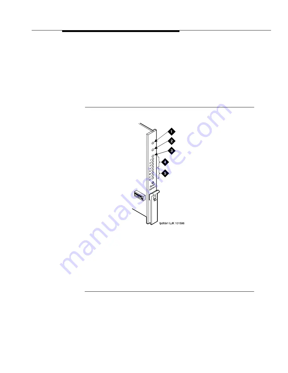
Below the three standard LEDs on the DS1C circuit pack are four green LEDs that
indicate whether a receive signal is present for each of the four DS1 facilities.
shows which facility (A, B, C, or D) corresponds to each LED. If a
green LED is off, there is a Loss of Signal condition on the DS1 facility associated
with that LED. The presence of a signal does not guarantee that the signal is
using the correct framing format or line coding; an Alarm Indication Signal
indicating that the opposite end of the DS1C complex is out of service may be
present.
Figure Notes:
1. Alarm LED (Red)
2. Test LED (Green)
3. Busy LED (Yellow)
4. STATUS LEDs
5. SPAN LEDs
Figure 6-2.
TN574 DS1 Converter Circuit Pack LEDs
Summary of Contents for S8700 Series
Page 50: ...Maintenance Architecture 555 233 143 1 26 Issue 1 May 2002 ...
Page 74: ...Initialization and Recovery 555 233 143 3 12 Issue 1 May 2002 ...
Page 186: ...Alarms Errors and Troubleshooting 555 233 143 4 112 Issue 1 May 2002 ...
Page 232: ...Additional Maintenance Procedures 555 233 143 5 46 Issue 1 May 2002 ...
Page 635: ...status psa Issue 1 May 2002 7 379 555 233 143 status psa See status tti on page 7 406 ...
Page 722: ...Maintenance Commands 555 233 143 7 466 Issue 1 May 2002 ...


