


MPX Redundancy
Page 2-9
MPX Redundancy
In order to provide greater reliability, Omni Switch/Router supports two
MPX
s in a
primary/secondary redundant configuration. If the primary
MPX
fails, the secondary
MPX
takes
over without any operator intervention.
♦
Warning
♦
Do
not
install any version of the
MPM
(i.e,
MPM-C
,
MPM 1G
,
MPM II
, or original
MPM
) in a chassis with an
MPX
. Installing an
MPM
in a chassis with an
MPX
can
cause physical damage. If you want to configure an
Omni Switch/Router chassis in a redundant configura-
tion, you
must
use two
MPXs
.
When you have two
MPX
s in one chassis, they must be installed in Slots 1 and 2, and only
one can be active.
MPX
s will assume one of the following roles.
• Primary - The
MPX
that is currently active and processing commands. It is also the
MPX
that
is communicating via Telnet,
FTP
, etc.
• Secondary - An
MPX
that is currently not the primary. It has sufficient software to commu-
nicate with the primary
MPX
. (For full redundancy, the secondary
MPX
should also have
the same software version as the primary and its configuration should be in sync with the
primary.) In this state, it is capable at any time of assuming the primary role.
The
LED
s on each
MPX
reflect the same status with the exception that the primary’s
PRI
LED
is
on whereas the secondary’s
SEC
LED
is on. Also, the secondary
MPX
’s
OK2
LED
will not flash
amber during board transitions. See
Omni Switch/Router Management Processor Module
(MPX) Status LEDs
on page 2-2 for locations of the
LEDs
.
♦
Important Note
♦
To support redundancy, your
MPX
must
be Revision
A14 or higher.
Change-Over Procedure
The secondary
MPX
continuously monitors the primary
MPX
. This monitoring serves two
purposes: 1) to notify the secondary
MPX
that the primary is alive and processing, and 2) to
update the configuration and thus keep the two
MPX
s in sync. If the secondary
MPX
detects
that the primary is no longer operational, it will begin to take over as primary. When a
secondary
MPX
becomes primary it resets all the other modules in the chassis and performs a
primary
MPX
initialization.
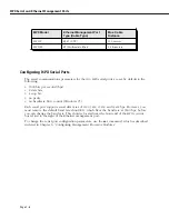
There are four states for an
MPX
configuration. You can view the current
MPX
state through
the
slot
command. These states are described in the table below. Note that for a
primary/secondary configuration to be in a “redundant” state, the relationship between the
two
MPX
s must meet the conditions shown in the table.
Summary of Contents for Omni Switch/Router
Page 1: ...Part No 060166 10 Rev C March 2005 Omni Switch Router User Manual Release 4 5 www alcatel com ...
Page 4: ...page iv ...
Page 110: ...WAN Modules Page 3 40 ...
Page 156: ...UI Table Filtering Using Search and Filter Commands Page 4 46 ...
Page 164: ...Using ZMODEM Page 5 8 ...
Page 186: ...Displaying and Setting the Swap State Page 6 22 ...
Page 202: ...Creating a New File System Page 7 16 ...
Page 270: ...Displaying Secure Access Entries in the MPM Log Page 10 14 ...
Page 430: ...OmniChannel Page 15 16 ...
Page 496: ...Configuring Source Route to Transparent Bridging Page 17 48 ...
Page 542: ...Dissimilar LAN Switching Capabilities Page 18 46 ...
Page 646: ...Application Example DHCP Policies Page 20 30 ...
Page 660: ...GMAP Page 21 14 ...
Page 710: ...Viewing the Virtual Interface of Multicast VLANs Page 23 16 ...
Page 722: ...Application Example 5 Page 24 12 ...
Page 788: ...Viewing UDP Relay Statistics Page 26 24 ...
Page 872: ...The WAN Port Software Menu Page 28 46 ...
Page 960: ...Deleting a PPP Entity Page 30 22 ...
Page 978: ...Displaying Link Status Page 31 18 ...
Page 988: ...Displaying ISDN Configuration Entry Status Page 32 10 ...
Page 1024: ...Backup Services Commands Page 34 14 ...
Page 1062: ...Diagnostic Test Cable Schematics Page 36 24 ...
Page 1072: ...Configuring a Switch with an MPX Page A 10 ...
Page 1086: ...Page B 14 ...
Page 1100: ...Page I 14 Index ...


