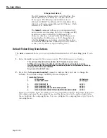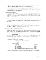
The Switch Menu
Page 18-33
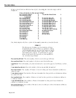
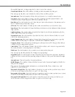
Transmitted Broadcasts
. The number of frames transmitted on this port whose destination
address is the broadcast address.
Note that these statistics merely indicate the format of the destination address of frames trans-
mitted/received on this port, not that the addressed device and/or devices necessarily reside
on that port. For example, unknown unicast addressed frames are flooded to many ports.
Received Buffer Discards
. Due to congestion of traffic from multiple ports on the board, timely
access to buffers was not available to receive a frame from the network port and the frame
was discarded.
Transmitted Buffer Discards
. Due to a shortage of buffers and/or congestion on the network
port, frames received from the backplane destined to this port were dropped.
Transmit Underflow
. Due to congestion of traffic from multiple ports on the board, timely
access to the buffer containing the frame currently being transmitted by this port was not
obtained and the frame had to be aborted and discarded.
vseTxDiscard
. Due to congestion of traffic from multiple ports and boards in the system, traf-
fic received from the network port could not be queued to the backplane due to buffer avail-
ability.
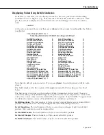
Received Collision Count, Received Runt Count
. These counts may be considered normal on a
shared segment (e.g., AUI and BNC connected Ethernet) where more than two stations exist.
The first indicates that a frame which the port started to receive from a station was subjected
to a collision from a third station. This is normal. Such collisions between third party stations
may cause this port to see fragments of a frame which are discarded as runts. This too is
normal on multiple station Ethernet segments. On point to point 10Base-T connections these
events may be considered abnormal indicating a possible intermittent wiring problem (unless
hubs which propagate fragments are in use.) These statistics do not indicate the loss of any
frame but rather events associated with the attempts to finally successfully transfer the frame.
Transmitted Defer Count, Transmitted Once Count, Transmitted More Count, and Transmitted Retry
Count
. These statistics are all related to collisions and deferral where this port is actively trying
to transmit a frame. The CSMA part of CSMA/CD, the protocol of Ethernet, requires that a
station which wishes to transmit first listens to the media to see if a transmission is already in
progress. If it is, then the station must defer transmission until the media is quiet. The Defer
count is the number of times this happens and is normal. A high defer count, relative to total
numbers of frames transmitted by the port, can be indicative of a busy segment. If a transmis-
sion is not in progress the station may begin to transmit. Due to propagation delays it is
possible for a station to suffer a collision from another station trying to transmit, even though
both listened for quiet media. When this occurs, both stations “back off” for a random time
before attempting transmission again. In theory, subsequent collisions may occur on these
retries. Once, More, and Retry indicate whether this is occurring. If a collision occurs but
succeeds on the retry, the Once counter is incremented, i.e., we collided once. If more than
one retry is required, the More count is incremented. If up to 16 retries are attempted and all
collide, then the frame is dropped and the Retry count is incremented. Again, Once, More,
and Retry are normal events on CSMA/CD media but high numbers, relative to total transmit-
ted frames, are again indicative of a very busy segment whose throughput could be increased
by further segmentation.
Received Error Discard
. A frame was received with an FCS and/or alignment error. A high
count here, relative to total received frames, is indicative of a noisy media subject to errors.
Loss Carrier Count
. This is a count of transmitted frames which are lost due to a loss of carrier.
This is indicative of poor quality/noisy wiring or adapter cards.
Summary of Contents for Omni Switch/Router
Page 1: ...Part No 060166 10 Rev C March 2005 Omni Switch Router User Manual Release 4 5 www alcatel com ...
Page 4: ...page iv ...
Page 110: ...WAN Modules Page 3 40 ...
Page 156: ...UI Table Filtering Using Search and Filter Commands Page 4 46 ...
Page 164: ...Using ZMODEM Page 5 8 ...
Page 186: ...Displaying and Setting the Swap State Page 6 22 ...
Page 202: ...Creating a New File System Page 7 16 ...
Page 270: ...Displaying Secure Access Entries in the MPM Log Page 10 14 ...
Page 430: ...OmniChannel Page 15 16 ...
Page 496: ...Configuring Source Route to Transparent Bridging Page 17 48 ...
Page 542: ...Dissimilar LAN Switching Capabilities Page 18 46 ...
Page 646: ...Application Example DHCP Policies Page 20 30 ...
Page 660: ...GMAP Page 21 14 ...
Page 710: ...Viewing the Virtual Interface of Multicast VLANs Page 23 16 ...
Page 722: ...Application Example 5 Page 24 12 ...
Page 788: ...Viewing UDP Relay Statistics Page 26 24 ...
Page 872: ...The WAN Port Software Menu Page 28 46 ...
Page 960: ...Deleting a PPP Entity Page 30 22 ...
Page 978: ...Displaying Link Status Page 31 18 ...
Page 988: ...Displaying ISDN Configuration Entry Status Page 32 10 ...
Page 1024: ...Backup Services Commands Page 34 14 ...
Page 1062: ...Diagnostic Test Cable Schematics Page 36 24 ...
Page 1072: ...Configuring a Switch with an MPX Page A 10 ...
Page 1086: ...Page B 14 ...
Page 1100: ...Page I 14 Index ...

