


Creating Multicast VLANs
Page 23-5
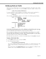
Step A. Entering Basic Information
1.
To begin setting up a multicast
VLAN
type
crmcvl
at any prompt.
2.
The following prompt displays:
Enter the VLAN Group id for this VLAN ( 1):
Enter the number for the Group to which this multicast
VLAN
will belong.You can create
up to
32
multicast
VLAN
s and up to 31 AutoTracker
VLAN
s in a single Group.
3.
The following prompt displays:
Enter the VLAN Id for this VLAN ( 5):
Enter the number that will identify this multicast
VLAN
within the Group specified above.
Up to 32 multicast
VLAN
s may belong to the same Group. By default the system displays
the next available
VLAN ID
number.
♦
Note
♦
Unlike AutoTracker
VLAN
s, you can configure rules for
the multicast
VLAN
#1. There is not a default multicast
VLAN
, so multicast
VLAN
#1 is treated the same as the
other 31 possible multicast
VLAN
s.
Press
<Enter>
to accept this default.
4.
The following prompt displays:
Enter the new VLAN’s description:
Enter a textual description that will help you identify the multicast
VLAN
. For example, if
you know this multicast
VLAN
will be composed of only workstations receiving
CNN
news
feeds, you might call the multicast
VLAN
“
CNN MVLAN
.” You may use up to 30 characters
for this description.
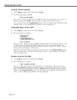
5.
The following prompt displays:
Enter the Admin Status for this vlan (Enable (e) / Disable (d):
Enter whether or not you want the Administrative Status for this multicast
VLAN
to be
enabled or disabled. Once enabled, the switch begins using the policies you defined. A
disabled multicast
VLAN
is still defined (name, number, policies intact), but the switch
keeps the multicast
VLAN
disabled. The enable/disable status may be changed at a later
time using the
modmcvl
command.
♦
Note
♦
A multicast
VLAN
may not always be operational even
when its Admin Status is enabled. A multicast
VLAN
’s
operation may be disabled by its switches because
devices in the multicast
VLAN
cease transmitting data,
among other reasons.
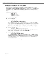
After you enter the administrative status, additional prompts display that allow you define
the multicast address. See the next section,
Step B. Defining the Multicast Address
on page
23-6 for further instructions.
Summary of Contents for Omni Switch/Router
Page 1: ...Part No 060166 10 Rev C March 2005 Omni Switch Router User Manual Release 4 5 www alcatel com ...
Page 4: ...page iv ...
Page 110: ...WAN Modules Page 3 40 ...
Page 156: ...UI Table Filtering Using Search and Filter Commands Page 4 46 ...
Page 164: ...Using ZMODEM Page 5 8 ...
Page 186: ...Displaying and Setting the Swap State Page 6 22 ...
Page 202: ...Creating a New File System Page 7 16 ...
Page 270: ...Displaying Secure Access Entries in the MPM Log Page 10 14 ...
Page 430: ...OmniChannel Page 15 16 ...
Page 496: ...Configuring Source Route to Transparent Bridging Page 17 48 ...
Page 542: ...Dissimilar LAN Switching Capabilities Page 18 46 ...
Page 646: ...Application Example DHCP Policies Page 20 30 ...
Page 660: ...GMAP Page 21 14 ...
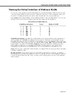
Page 710: ...Viewing the Virtual Interface of Multicast VLANs Page 23 16 ...
Page 722: ...Application Example 5 Page 24 12 ...
Page 788: ...Viewing UDP Relay Statistics Page 26 24 ...
Page 872: ...The WAN Port Software Menu Page 28 46 ...
Page 960: ...Deleting a PPP Entity Page 30 22 ...
Page 978: ...Displaying Link Status Page 31 18 ...
Page 988: ...Displaying ISDN Configuration Entry Status Page 32 10 ...
Page 1024: ...Backup Services Commands Page 34 14 ...
Page 1062: ...Diagnostic Test Cable Schematics Page 36 24 ...
Page 1072: ...Configuring a Switch with an MPX Page A 10 ...
Page 1086: ...Page B 14 ...
Page 1100: ...Page I 14 Index ...


