Application Example 2
Page 24-5
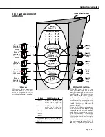
12345678
123456
Omni Switch/Router
IPX
Client
VLAN
Membership
Client 1
both B & C initially, then
either B or C when net-
work number is known
Client 2
both B & C initially, then
either B or C when net-
work number is known
Client 3
D
Client 4
E
Client 5
F
Please note that all ports in Group 3
are also members of Group 3’s default
VLAN
#1.
IPX
Servers
Internal
IPX
Router
IPX
Client Workstations
Port 1
Port 5
Port 4
Port 3
Port 2
Port 10
Port 9
Client 1
Ethernet-
II
encap
Client 2
Ethernet-
II
encap
Client 3
802.2
encap
Client 4
SNAP
encap
Client 5
802.3
encap
Server 1
Network 10
Ethernet-
II
encap
Server 2
Network 20
Ethernet-
II
encap
Server 3
Network 30
802.2 encap
Server 4
Network 40
SNAP
encap
Server 5
Network 50
802.3 encap
VLAN
E
IPX
Network 40
SNAP
encap
VLAN
F
IPX
Network 50
IPX
802.3 encap
VLAN
D
IPX
Network 30
802.2 encap
VLAN
B
IPX
Network 10
Ethernet-
II
encap
VLAN
C
IPX
Network 20
Ethernet-
II
encap
Group 3
Ports 1 – 10
network 10
network 20
network 30
network 40
network 50
t 9
Port 6
Port 7
Port 8
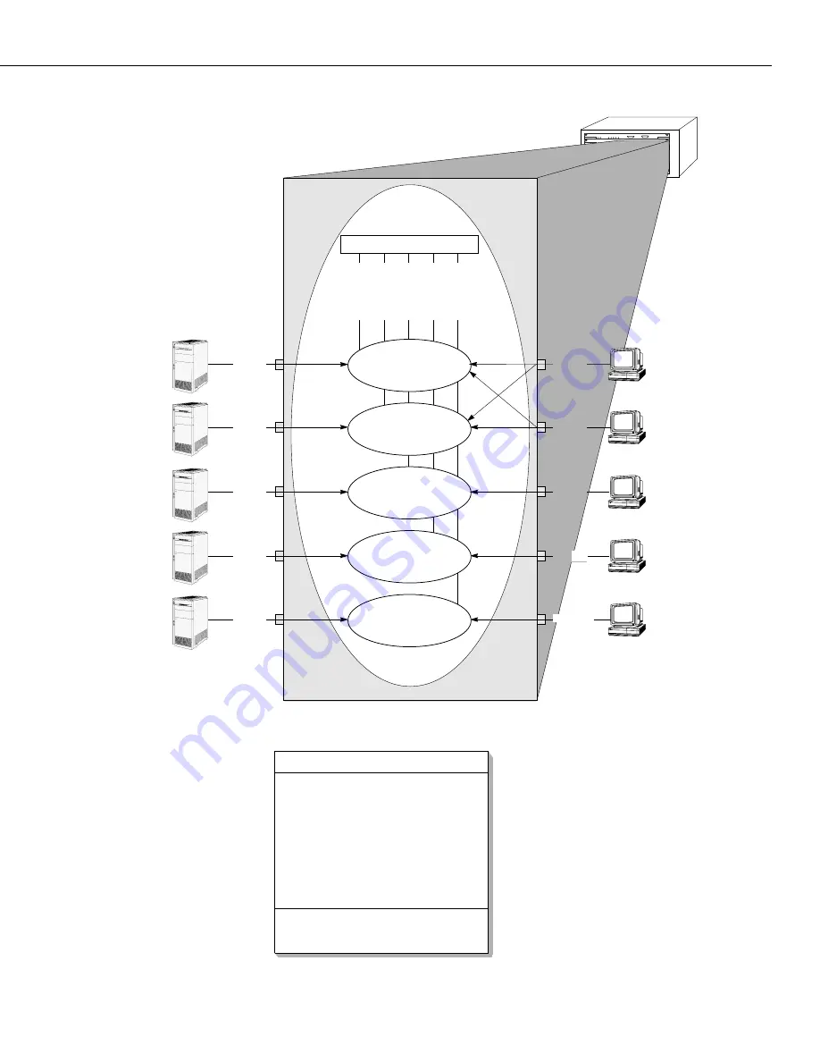
When
IPX
clients boot up, their
encapsulation types are known
but their network numbers are
not. Therefore,
IPX
clients are ini-
tially assigned to
VLAN
s accord-
ing to encapsulation type. This is
the reason Clients 1 and 2 (which
use Ethernet-
II
encapsulation) are
a s s i g n e d t o
V L A N
s B a n d C
(which both specify Ethernet-
II
encapsulation).
Once an
IPX
client communicates
with a server or an intervening
router, learns its network number
and begins transmitting frames
with that number, it is removed
from all previously-assigned
IPX
VLAN
s and placed into a single
IPX VLAN
according to network
number. Client 1 and Client 2 will
be reassigned to either
VLAN
B
or
VLAN
C when their respective
network numbers are known.
IPX
servers always know their
network number, so
IPX
serv-
ers are assigned to
VLAN
s
according to network number.
IPX
VLAN
Assignment
at Bootup
Summary of Contents for Omni Switch/Router
Page 1: ...Part No 060166 10 Rev C March 2005 Omni Switch Router User Manual Release 4 5 www alcatel com ...
Page 4: ...page iv ...
Page 110: ...WAN Modules Page 3 40 ...
Page 156: ...UI Table Filtering Using Search and Filter Commands Page 4 46 ...
Page 164: ...Using ZMODEM Page 5 8 ...
Page 186: ...Displaying and Setting the Swap State Page 6 22 ...
Page 202: ...Creating a New File System Page 7 16 ...
Page 270: ...Displaying Secure Access Entries in the MPM Log Page 10 14 ...
Page 430: ...OmniChannel Page 15 16 ...
Page 496: ...Configuring Source Route to Transparent Bridging Page 17 48 ...
Page 542: ...Dissimilar LAN Switching Capabilities Page 18 46 ...
Page 646: ...Application Example DHCP Policies Page 20 30 ...
Page 660: ...GMAP Page 21 14 ...
Page 710: ...Viewing the Virtual Interface of Multicast VLANs Page 23 16 ...
Page 722: ...Application Example 5 Page 24 12 ...
Page 788: ...Viewing UDP Relay Statistics Page 26 24 ...
Page 872: ...The WAN Port Software Menu Page 28 46 ...
Page 960: ...Deleting a PPP Entity Page 30 22 ...
Page 978: ...Displaying Link Status Page 31 18 ...
Page 988: ...Displaying ISDN Configuration Entry Status Page 32 10 ...
Page 1024: ...Backup Services Commands Page 34 14 ...
Page 1062: ...Diagnostic Test Cable Schematics Page 36 24 ...
Page 1072: ...Configuring a Switch with an MPX Page A 10 ...
Page 1086: ...Page B 14 ...
Page 1100: ...Page I 14 Index ...


