Modifying a Group or VLAN
Page 19-40
Modifying a Group or VLAN
After creating a Group (through
crgp
) or
VLAN (
through
cratvl
, see Chapters 20 and 22
)
, you
can change any of their parameters through the
modvl
command. In addition, if you did not
set up a virtual router port (
IP
or
IPX
) during the initial Group or
VLAN
configuration, you can
set one up with
modvl
. To use this command, enter
modvl
followed by the Group number and
VLAN
number to change. For example, to modify parameters in Group 2,
VLAN
1, enter:
modvl 2
Note that you do not need to specify a
VLAN
number to modify the default
VLAN
within a
Group. To modify parameters in Group 2,
VLAN
2, you would enter:
modvl 2:2
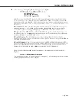
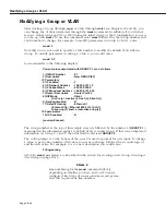
A screen similar to the following displays.
Current values associated with GROUP 2.1 are as follows:
1) GROUP Number
- 2:1
2) Description
- New GROUP (#2)
IP Parameters:
3) IP enabled
- Y
4) IP Network Address
- 198.206.101.12
5) IP Subnet Mask
- 255.255.255.0
6) IP Broadcast Address - 198.206.101.255
7) Router Description
- Router Port #2
8) RIP Mode
- Silent
{Active (a), Inactive (i), Deaf (d), Silent (s)}
9) Routing disabled
- N
11) Default Framing
- Ethernet II
{Ethernet II(e), Ethernet 802.3 (8), fddi (f),
token ring (t), source route token ring (s)}
IPX parameters:
12) IPX enabled
- N
(save/quit/cancel)
:
The Group number at the top of this sample screen is followed by the number 1 (
GROUP 2.1
),
meaning that the information applies to default
VLAN #1
in this Group. If this screen displayed
information on Group 2,
VLAN
2, then this field would read
GROUP 2:2
.
The colon prompt (:) at the bottom of the screen is used to prompt for user input. To change
a value, type the line number of the item you want to change, followed by an equal sign (=)
and the new value. For example, to set a new description you could enter:
2=Engineering
All of the
modvl
parameters are described in the section for creating a new Group,
Creating a
New Group
on page 19-18.
♦
Note
♦
Line numbering for the
modvl
command will vary
depending on whether you have an
IP
or
IPX
router
configured. Each type of router contains several param-
eters that require extra line numbers.
Summary of Contents for Omni Switch/Router
Page 1: ...Part No 060166 10 Rev C March 2005 Omni Switch Router User Manual Release 4 5 www alcatel com ...
Page 4: ...page iv ...
Page 110: ...WAN Modules Page 3 40 ...
Page 156: ...UI Table Filtering Using Search and Filter Commands Page 4 46 ...
Page 164: ...Using ZMODEM Page 5 8 ...
Page 186: ...Displaying and Setting the Swap State Page 6 22 ...
Page 202: ...Creating a New File System Page 7 16 ...
Page 270: ...Displaying Secure Access Entries in the MPM Log Page 10 14 ...
Page 430: ...OmniChannel Page 15 16 ...
Page 496: ...Configuring Source Route to Transparent Bridging Page 17 48 ...
Page 542: ...Dissimilar LAN Switching Capabilities Page 18 46 ...
Page 646: ...Application Example DHCP Policies Page 20 30 ...
Page 660: ...GMAP Page 21 14 ...
Page 710: ...Viewing the Virtual Interface of Multicast VLANs Page 23 16 ...
Page 722: ...Application Example 5 Page 24 12 ...
Page 788: ...Viewing UDP Relay Statistics Page 26 24 ...
Page 872: ...The WAN Port Software Menu Page 28 46 ...
Page 960: ...Deleting a PPP Entity Page 30 22 ...
Page 978: ...Displaying Link Status Page 31 18 ...
Page 988: ...Displaying ISDN Configuration Entry Status Page 32 10 ...
Page 1024: ...Backup Services Commands Page 34 14 ...
Page 1062: ...Diagnostic Test Cable Schematics Page 36 24 ...
Page 1072: ...Configuring a Switch with an MPX Page A 10 ...
Page 1086: ...Page B 14 ...
Page 1100: ...Page I 14 Index ...

