Hot Swapping a Switching Module
Page 3-8
4.
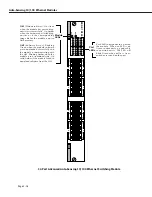
Carefully remove the switching module from the chassis and put it in a safe place. (See
Removing a Switching Module
on page 3-6 for instructions on removing a switching
module.) The
MPX’s
OK2
LED
will flash amber 1 or 2 times, then return to normal flashing
green. In addition, the swap time will reset to its original value. (For example, if you set
the swap time to 15 minutes in step 1, you will have 15 minutes again, regardless of how
much time has elapsed.)
♦
Warning
♦
Removing or inserting the switching module while the
MPX’s
OK2
LED
is flashing amber can cause the system
to reset.
5.
Carefully insert the new switching module into the chassis. (See
Installing a Switching
Module
on page 3-4 for instructions on inserting a switching module.)
♦
Caution
♦
When re-installing a module during a hot swap, it must
make a proper connection to the switch backplane.
The connection is made when you close the card ejec-
tors. Always close the card ejectors firmly and briskly,
without hesitation. Closing them too slowly can cause
the switch to halt or restart.
The
MPX’s
OK2
LED
will flash amber 1 or 2 times, then return to normal flashing green. If,
after hot-swapping modules, the
MPX’s
OK2
LED
continues to flash amber for more than
about 8 seconds, it means that the switch needs to be reset.
The swap time will again reset to its original value.
6.
Re-insert the cables that were removed in step 3 into the new switching module.
7.
Enter
reset
followed by the slot number for the new switching module. For example, if
the new switching module is in slot 4, you would enter
reset 4
at the system prompt. Next, the switch will prompt you to confirm the reset. The follow-
ing is an example of the display for an
ESX
module. The display for other types of switch-
ing modules will be similar.
Resetting slot of type F-Ether/M may crash system
Attempt reset anyway {Y/N}? (N) :
Press
y
and then press
<Enter>
. If the switching module is in slot 4, a message similar to
the following will be displayed.
resetting slot 4 to enable
8.
The
MPX’s
OK2
LED
will flash amber 1 or 2 times, then return to normal flashing green.
The switching module’s
OK1
LED
will turn from amber to solid green and the
OK2
LED
will be blinking green. If the
OK1
LED
on the switching module is amber, then the hard-
ware has failed diagnostics or the corresponding image file for the module is not in flash
memory. If the
OK2
LED
on the switching module is solid amber, then the module failed
to download software from the
MPX
.
Summary of Contents for Omni Switch/Router
Page 1: ...Part No 060166 10 Rev C March 2005 Omni Switch Router User Manual Release 4 5 www alcatel com ...
Page 4: ...page iv ...
Page 110: ...WAN Modules Page 3 40 ...
Page 156: ...UI Table Filtering Using Search and Filter Commands Page 4 46 ...
Page 164: ...Using ZMODEM Page 5 8 ...
Page 186: ...Displaying and Setting the Swap State Page 6 22 ...
Page 202: ...Creating a New File System Page 7 16 ...
Page 270: ...Displaying Secure Access Entries in the MPM Log Page 10 14 ...
Page 430: ...OmniChannel Page 15 16 ...
Page 496: ...Configuring Source Route to Transparent Bridging Page 17 48 ...
Page 542: ...Dissimilar LAN Switching Capabilities Page 18 46 ...
Page 646: ...Application Example DHCP Policies Page 20 30 ...
Page 660: ...GMAP Page 21 14 ...
Page 710: ...Viewing the Virtual Interface of Multicast VLANs Page 23 16 ...
Page 722: ...Application Example 5 Page 24 12 ...
Page 788: ...Viewing UDP Relay Statistics Page 26 24 ...
Page 872: ...The WAN Port Software Menu Page 28 46 ...
Page 960: ...Deleting a PPP Entity Page 30 22 ...
Page 978: ...Displaying Link Status Page 31 18 ...
Page 988: ...Displaying ISDN Configuration Entry Status Page 32 10 ...
Page 1024: ...Backup Services Commands Page 34 14 ...
Page 1062: ...Diagnostic Test Cable Schematics Page 36 24 ...
Page 1072: ...Configuring a Switch with an MPX Page A 10 ...
Page 1086: ...Page B 14 ...
Page 1100: ...Page I 14 Index ...


