Remote Network Monitoring (RMON)
Page 14-3
Remote Network Monitoring (RMON)
Remote Network Monitoring (
RMON
) allows you to set up remote monitoring within your
Omni Switch/Router.
RMON
consists of “probes” and “events.” There are two commands in
the Networking menu,
probes
and
events
, which you can use to monitor, activate and inacti-
vate probes and events. Be aware that you cannot create probes from within the switch’s User
Interface; to do so requires a network application such as
HP
ProbeView.
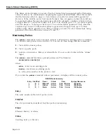
Probes and Events
A
probe
is a task that runs in the switch. By using probes instead of sending repetitive inquir-
ies to the switch, network traffic is significantly reduced.
There are three different kinds of probes: Ethernet, History, and Alarm.
A network management station (
NMS
) can configure either History or Alarm probes (a maxi-
mum of 16 is allowed). The status of a probe can be one of the following:
• Creating - The probe is under creation.
• Active - The probe is active.
• Inactive - The probe is inactive.
An
event
is an action that takes place based on an alarm condition detected by a probe. The
event can take the form of an
SNMP
trap message and/or a log entry describing the alarm.
Ethernet Probes
An Ethernet probe monitors a selected Ethernet interface (port) and tracks Ethernet statistics.
An Ethernet probe is automatically created on each Ethernet interface that is enabled. If the
interface becomes disabled, that Ethernet probe is deleted.
History Probes
A History probe keeps a running history of all the statistics it has collected. When you set up
a history probe you assign a sampling interval and a total number of samples to be taken. It
keeps this information in a set of rotating buffers, so that it always retains the most recent
samples.
The sampling rate is configurable from 1 second to 3600 seconds (1 hour). The total number
of samples is configurable, however, it is limited by system resources (memory) available. The
more samples you request, the more system resources needed. You may request as many
samples as you want but the system will only grant as many as it has available.
Alarm Probes
An Alarm probe generates an alarm if the variable you are monitoring exceeds a set limit.
To set up an Alarm probe you need to select a variable (Ethernet statistic) that you want to
monitor. You set an upper and lower threshold that you will allow this variable to reach. If it
crosses the threshold, an event is triggered which results in the sending of an
SNMP
trap and/
or the logging of the alarm.
There are two ways an Alarm probe monitors variables. One is by absolute value. For exam-
ple, if you set an upper limit of 100, an alarm will be generated if the variable exceeds 100.
The other is a delta value where you can set the amount of change allowable; for example,
you could set the delta range to 10. If the current sample differs from the previous sample by
more than 10, an alarm will be generated.
Summary of Contents for Omni Switch/Router
Page 1: ...Part No 060166 10 Rev C March 2005 Omni Switch Router User Manual Release 4 5 www alcatel com ...
Page 4: ...page iv ...
Page 110: ...WAN Modules Page 3 40 ...
Page 156: ...UI Table Filtering Using Search and Filter Commands Page 4 46 ...
Page 164: ...Using ZMODEM Page 5 8 ...
Page 186: ...Displaying and Setting the Swap State Page 6 22 ...
Page 202: ...Creating a New File System Page 7 16 ...
Page 270: ...Displaying Secure Access Entries in the MPM Log Page 10 14 ...
Page 430: ...OmniChannel Page 15 16 ...
Page 496: ...Configuring Source Route to Transparent Bridging Page 17 48 ...
Page 542: ...Dissimilar LAN Switching Capabilities Page 18 46 ...
Page 646: ...Application Example DHCP Policies Page 20 30 ...
Page 660: ...GMAP Page 21 14 ...
Page 710: ...Viewing the Virtual Interface of Multicast VLANs Page 23 16 ...
Page 722: ...Application Example 5 Page 24 12 ...
Page 788: ...Viewing UDP Relay Statistics Page 26 24 ...
Page 872: ...The WAN Port Software Menu Page 28 46 ...
Page 960: ...Deleting a PPP Entity Page 30 22 ...
Page 978: ...Displaying Link Status Page 31 18 ...
Page 988: ...Displaying ISDN Configuration Entry Status Page 32 10 ...
Page 1024: ...Backup Services Commands Page 34 14 ...
Page 1062: ...Diagnostic Test Cable Schematics Page 36 24 ...
Page 1072: ...Configuring a Switch with an MPX Page A 10 ...
Page 1086: ...Page B 14 ...
Page 1100: ...Page I 14 Index ...


