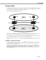
Port Mapping
Page 19-67
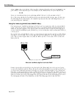
Port communication is uni-directional. A mapping between an ingress port and an egress port
can only pass data from the ingress port to the egress port. To allow traffic to flow the from
the egress port to the ingress port, it is necessary to create a new mapping.
This configuration restricts each port to communication
only with the other four ports in the
opposite port mapping subset within the same group
. For example, port 2/1 can only send traf-
fic to ports 5/1, 5/2, 5/3, and 5/4. It can no longer communicate with ports 2/2, 2/3, and 2/4
even though they are part of the same group. Port mapping restricts ports from communicat-
ing with other ports within the same subset.
Port mapping does not affect other ports in the group that are not part of the port mapping
set.
The Details of Port Mapping
Port mapping can be thought of as special rule that is applied after standard group and
VLAN
rules are applied. This rule statically assigns a port as either an ingress or egress port. Ingress
ports can only communicate with egress ports. In this sense, one subset of ports is “mapped”
to another subset of ports. Ports within the same subset can not communicate with each other
or with another switch port that is not a member of the opposite port mapping subset.
♦
Note
♦
Port mapping restrictions are only applied to ports on
10/100 Ethernet modules (e.g., ESM-100F-8, ESM-C-32,
ESM-FM-16W, ESM-100C-12).
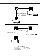
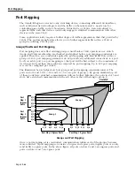
As an illustration, see the diagram of three Ethernet modules below. The modules are in slots
2, 3, and 4. The ports that are circled are included in a port mapping subset. The three ports
at the top—2/1, 3/1, and 4/1—are ingress ports. The six ports below —2/4, 2/5, 3/4, 3/5, 4/4,
and 4/5—are egress ports in the port mapping set.
Port Subsets in the Port Mapping Set
1x
6x
2x
3x
4x
5x
7x
8x
6
7
12
8
9
10
11
LNK ACT
1x
6x
2x
3x
4x
5x
7x
8x
6
7
12
8
9
10
11
LNK ACT
1x
6x
2x
3x
4x
5x
7x
8x
6
7
12
8
9
10
11
LNK ACT
Slo
t 2
Slo
t 3
Slo
t 4
One side of the
paired set. Ports
2/1, 3/1, and 4/1.
These ports are
subset A.
Other side of the
paired set. Ports
2/4, 2/5, 3/4, 3/5,
4 / 4 , a n d 4 / 5 .
These ports are
subset B.
Summary of Contents for Omni Switch/Router
Page 1: ...Part No 060166 10 Rev C March 2005 Omni Switch Router User Manual Release 4 5 www alcatel com ...
Page 4: ...page iv ...
Page 110: ...WAN Modules Page 3 40 ...
Page 156: ...UI Table Filtering Using Search and Filter Commands Page 4 46 ...
Page 164: ...Using ZMODEM Page 5 8 ...
Page 186: ...Displaying and Setting the Swap State Page 6 22 ...
Page 202: ...Creating a New File System Page 7 16 ...
Page 270: ...Displaying Secure Access Entries in the MPM Log Page 10 14 ...
Page 430: ...OmniChannel Page 15 16 ...
Page 496: ...Configuring Source Route to Transparent Bridging Page 17 48 ...
Page 542: ...Dissimilar LAN Switching Capabilities Page 18 46 ...
Page 646: ...Application Example DHCP Policies Page 20 30 ...
Page 660: ...GMAP Page 21 14 ...
Page 710: ...Viewing the Virtual Interface of Multicast VLANs Page 23 16 ...
Page 722: ...Application Example 5 Page 24 12 ...
Page 788: ...Viewing UDP Relay Statistics Page 26 24 ...
Page 872: ...The WAN Port Software Menu Page 28 46 ...
Page 960: ...Deleting a PPP Entity Page 30 22 ...
Page 978: ...Displaying Link Status Page 31 18 ...
Page 988: ...Displaying ISDN Configuration Entry Status Page 32 10 ...
Page 1024: ...Backup Services Commands Page 34 14 ...
Page 1062: ...Diagnostic Test Cable Schematics Page 36 24 ...
Page 1072: ...Configuring a Switch with an MPX Page A 10 ...
Page 1086: ...Page B 14 ...
Page 1100: ...Page I 14 Index ...

