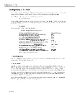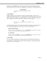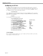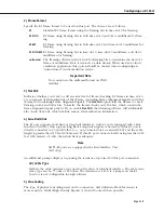
T1 and E1 Overview
Page 33-2
T1 and E1 Overview
Carrier digital services were designed primarily to support digitized voice over long distances.
Digital services are the primary method for carrying voice between two endpoints using two
pairs of copper wire. Digital wide-area data networking uses the same digital services that
were originally designed for digitized voice.
Analog to Digital Conversion
To improve quality and reliability, long-distance phone networks upgraded their backbones
from analog Frequency Division Multiplexing (
FDM
) to digital Time Division Multiplexing
(
TDM
). In
TDM
, analog data is converted to digital data using a
CODEC
device that employs a
method called Pulse Code Modulation (
PCM
).
In Pulse Code Modulation, the
CODEC
samples the analog signal 8,000 times a second and
converts each sample to an 8-bit digital value. These 8,000 8-bit samples yield a total digital
data rate of
64
,
000 BPS
for one voice service. This service is also known as Digital Service
Zero (
DS0
), which is the basis for T1 and E1 connections.
These 8,000 8-bits in time are also known as a
time slot
. A
channel
is a time slot that can
carry voice or data. Using Time Division Multiplexing,
24
channels (for
T1)
or 32 channels (for
E1)
are multiplexed to create a service called Digital Service 1 (
DS1
). The more common name
for
DS1
is
T1
or
E1
.
T1 Framing
A T1 frame consists of 24, 8-bit time slots and a 1-bit synchronization and control bit. Twelve
(12) T1 frames can be grouped into a
SuperFrame (SF/D4)
, or 24 T1 frames can be grouped
into an
Extended SuperFrame
. In each SuperFrame, the 6th and 12th frame may contain
“robbed bit” (A, B) signalling, which means the least significant bit is robbed from each time
slot in the 6th and 12th frame and used for signalling. In Extended SuperFrames, this robbed-
bit signalling (A, B, C, D) occurs in the 6th, 12th, 18th, and 24th frames.
E1 Framing
The E1 frame consists of 32, 8-bit time slots (two of these time slots are used for synchroniza-
tion and multiframe signalling) for 256 bits per frame at 2.048 megabits per second. Sixteen
(16) E1 frames are grouped into a multiframe. An E1 multiframe can use Channel Associated
Signalling (
CAS
) contained in time slot 16. Timeslot 16 in multiframe 0 is used for multiframe
synchronization and control. Timeslot 16 of multiframes 1 through 15 are used to carry A, B,
C, and D signaling bits.
Summary of Contents for Omni Switch/Router
Page 1: ...Part No 060166 10 Rev C March 2005 Omni Switch Router User Manual Release 4 5 www alcatel com ...
Page 4: ...page iv ...
Page 110: ...WAN Modules Page 3 40 ...
Page 156: ...UI Table Filtering Using Search and Filter Commands Page 4 46 ...
Page 164: ...Using ZMODEM Page 5 8 ...
Page 186: ...Displaying and Setting the Swap State Page 6 22 ...
Page 202: ...Creating a New File System Page 7 16 ...
Page 270: ...Displaying Secure Access Entries in the MPM Log Page 10 14 ...
Page 430: ...OmniChannel Page 15 16 ...
Page 496: ...Configuring Source Route to Transparent Bridging Page 17 48 ...
Page 542: ...Dissimilar LAN Switching Capabilities Page 18 46 ...
Page 646: ...Application Example DHCP Policies Page 20 30 ...
Page 660: ...GMAP Page 21 14 ...
Page 710: ...Viewing the Virtual Interface of Multicast VLANs Page 23 16 ...
Page 722: ...Application Example 5 Page 24 12 ...
Page 788: ...Viewing UDP Relay Statistics Page 26 24 ...
Page 872: ...The WAN Port Software Menu Page 28 46 ...
Page 960: ...Deleting a PPP Entity Page 30 22 ...
Page 978: ...Displaying Link Status Page 31 18 ...
Page 988: ...Displaying ISDN Configuration Entry Status Page 32 10 ...
Page 1024: ...Backup Services Commands Page 34 14 ...
Page 1062: ...Diagnostic Test Cable Schematics Page 36 24 ...
Page 1072: ...Configuring a Switch with an MPX Page A 10 ...
Page 1086: ...Page B 14 ...
Page 1100: ...Page I 14 Index ...

