Virtual Circuits and DLCIs
Page 29-6
Virtual Circuits and DLCIs
The
WSX
supports Permanent Virtual Circuits (
PVCs
), but not Switched Virtual Circuits (
SVCs
).
Most service carriers do not currently offer
SVCs
.
PVCs
are either static (configured) or
dynamic (learned). Static
PVCs
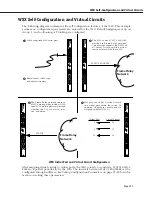
are user-configured and consist of Management, or Control,
PVCs
and any configured Data
PVC
s. Management VCs are used by the
WSX
to communicate
with the Frame Relay network. Dynamic
PVCs
are usually data circuits, which are controlled
by the Frame Relay network and not configured in advance. A logical Frame Relay
DTE
device like the
WSX
does not create or control dynamic data VCs. It is only informed of their
status through periodic Status updates from the Frame Relay network.
Each virtual circuit is locally defined by a Data Link Connection Identifier (
DLCI
). The Frame
Relay network assigns the
DLCIs
and informs the
WSX
about them.
DLCI
numbers from 0 to 15 and 992 to 1023 are reserved for Control VCs. If you are using
Annex A or Annex D as your
DLCMI
, the management control VC will be assigned DLCI 0. If
you are using the LMI Revision 1.0
DLCMI
, then the management control VC will be assigned
DLCI 1023
.
DLCI
numbers from 16 to 991 are reserved for Data VCs.
You may have up to 256 virtual circuits and up to 128 virtual ports on a
WSX
.
A VC may or may not have the same
DLCI
on each side of a
WAN
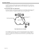
link. For example, if a
WSX
physical port contains three Frame Relay VCs on its local network with
DLCIs
16, 17, and 18,
these same VCs on the other side of the Frame Relay network might be 30, 31, and 32. The
two sets of
DLCIs
are technically part of the same virtual circuits, but their values may or may
not be different.
DLCIs
are only significant locally.
At any one time, a virtual circuit will be active, inactive or deleted. If a virtual circuit is Active
it can transmit and receive data. If it is Inactive, the Frame Relay network still sees the virtual
circuit, but there is a problem with it and it is discarding data. If the virtual circuit is Deleted,
then the virtual circuit is not transmitting or receiving data and no
DLCI
exists for it.
Summary of Contents for Omni Switch/Router
Page 1: ...Part No 060166 10 Rev C March 2005 Omni Switch Router User Manual Release 4 5 www alcatel com ...
Page 4: ...page iv ...
Page 110: ...WAN Modules Page 3 40 ...
Page 156: ...UI Table Filtering Using Search and Filter Commands Page 4 46 ...
Page 164: ...Using ZMODEM Page 5 8 ...
Page 186: ...Displaying and Setting the Swap State Page 6 22 ...
Page 202: ...Creating a New File System Page 7 16 ...
Page 270: ...Displaying Secure Access Entries in the MPM Log Page 10 14 ...
Page 430: ...OmniChannel Page 15 16 ...
Page 496: ...Configuring Source Route to Transparent Bridging Page 17 48 ...
Page 542: ...Dissimilar LAN Switching Capabilities Page 18 46 ...
Page 646: ...Application Example DHCP Policies Page 20 30 ...
Page 660: ...GMAP Page 21 14 ...
Page 710: ...Viewing the Virtual Interface of Multicast VLANs Page 23 16 ...
Page 722: ...Application Example 5 Page 24 12 ...
Page 788: ...Viewing UDP Relay Statistics Page 26 24 ...
Page 872: ...The WAN Port Software Menu Page 28 46 ...
Page 960: ...Deleting a PPP Entity Page 30 22 ...
Page 978: ...Displaying Link Status Page 31 18 ...
Page 988: ...Displaying ISDN Configuration Entry Status Page 32 10 ...
Page 1024: ...Backup Services Commands Page 34 14 ...
Page 1062: ...Diagnostic Test Cable Schematics Page 36 24 ...
Page 1072: ...Configuring a Switch with an MPX Page A 10 ...
Page 1086: ...Page B 14 ...
Page 1100: ...Page I 14 Index ...


