background image

WAN Modules

Page 3-26

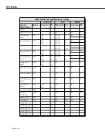
WAN Serial Port Specifications (cont.)

X.21/X.26

V.35

RS232

Generic 
Signal Name

Source

Mnemonic Pin

Mnemonic Pin

Mnemonic Pin

Shield

--

--

1

--

A

--

1

Signal Ground

--

G

8

102

B

AB

7

Transmitted 
Data

DTE

T(A)

2

103(A)

P

BA

2

T(B)

9

103(B)

S

Received Data

DCE

R(A)

4

104(A)

R

BB

3

R(B)

11

104(B)

T

Transmit Clock DCE

--

--

114(A)

Y

DB

15

114(B)

AA

Receive Clock

DCE

S(A)

6

115(A)

V

DD

17

S(B)

13

115(B)

X

Ext. Transmit 
Clock

DTE

B(A)

7

113(A)

U

DA

24

B(B)

14

113

W

Request To 
Send

DTE

C(A)

3

105

C

CA

4

C(B)

10

Clear To Send

DCE

--

--

106

D

CB

5

Data Set Ready DCE

--

--

107

E

CC

6

Data Terminal 
Ready

DTE

--

--

108

H

CD

20

Data Carrier 
Detect

DCE

I(A)

5

109

F

CF

8

I(B)

12

Local Loopback DTE

--

--

141

L

LL

18

Remote 
Loopback

DTE

--

--

140

N

RL

21

Ring Indicator

DCE

--

--

125

J

CE

22

Test Mode

DCE

--

--

142

NN

TM

25

Cable Type 4

--

n/c

n/c

Cable Type 3

--

n/c

n/c

Cable Type 2

--

Cable Type 1

--

Cable Type 0

--

Summary of Contents for Omni Switch/Router

Page 1: ...Part No 060166 10 Rev C March 2005 Omni Switch Router User Manual Release 4 5 www alcatel com ...

Page 2: ...scribed in this Manual is subject to change without notice 26801 West Agoura Road Calabasas CA 91301 818 880 3500 FAX 818 880 3505 info ind alcatel com US Customer Support 800 995 2696 International Customer Support 818 878 4507 Internet http eservice ind alcatel com An Alcatel service agreement brings your company the assurance of 7x24 no excuses technical support You ll also receive regular soft...

Page 3: ... suggested that the user use only shielded and grounded cables to ensure compliance with FCC Rules This equipment does not exceed Class A limits per radio noise emissions for digital apparatus set out in the Radio Interference Regulation of the Canadian Department of Communications Avis de conformité aux normes du ministére des Communications du Canada Cet équipement ne dépasse pas les limites de ...

Page 4: ...page iv ...

Page 5: ...ications 1 15 OmniS R 9P Technical Specifications 1 16 OmniS R 9P 48V Technical Specifications 1 17 Omni Switch Router Power Requirements 1 18 Grounding a Chassis 1 21 The Omni Switch Router Hardware Routing Engine HRE X 1 22 Valid HRE X Configurations 1 23 HRE X Router Registers versus Feature Limitations 1 23 Connecting a DC Power Source to an OmniS R PS5 DC375 1 24 Installing DC Power Source Wi...

Page 6: ...et RJ 45 Pinouts 3 15 Ethernet RJ 45 Specifications 3 15 ESX K 100C 32W 3 15 ESX K 100C 32W Technical Specifications 3 17 Fast 100 Mbps Ethernet Modules 3 19 ESX K 100FM FS 16W 3 19 ESX K 100FM FS 16W Technical Specifications 3 20 WAN Modules 3 22 WAN Pinouts 3 22 WAN BRI Port Specifications S T Interface 3 23 WAN BRI Port Specifications U Interface 3 23 WAN T1 E1 Port Specifications 3 24 WAN Seri...

Page 7: ...1 Troubleshooting Diagnostics Commands 4 13 Troubleshooting Diagnostics Table 4 13 User Interface Menu 4 14 Main Menu Summary 4 15 General User Interface Guidelines 4 16 Entering Command Names 4 16 Quitting a Command 4 17 Scrolling 4 17 The UI Configuration Menu 4 17 Configuring the System Prompt 4 18 Configuring More Mode for the User Interface 4 19 Setting Verbose Terse Mode for the User Interfa...

Page 8: ...ing Serial Port Communication Parameters 6 2 Changing Port Speed When Communication With The Switch Lost 6 3 Configuring the Modem Port 6 3 Modem Port Mode 6 3 Configuring SLIP 6 4 Configuring the Ethernet Management Port 6 5 Ethernet Management Ports and Redundant Management Processor Modules 6 7 The MPM Command Menu 6 9 Displaying MPX Redundancy 6 9 MPM Menu Commands 6 9 Using MPM Commands with ...

Page 9: ...iles 7 4 Deleting All Image Files 7 5 Copying System Files 7 6 Displaying Text Files 7 6 Editing Text Files 7 7 Clearing the Text Buffer 7 7 Loading an ASCII File into the Text Buffer 7 8 Listing the Contents of the Text Buffer 7 8 Adding Lines of Text to the Text Buffer 7 8 Deleting a Line of Text from the Text Buffer 7 9 Inserting a Line of Text into the Text Buffer 7 9 Editing a Line Name of Te...

Page 10: ...9 Modifying a User Account 8 20 Deleting a User 8 20 9 Configuring Switch Wide Parameters 9 1 Summary Menu 9 1 Displaying the MIB II System Group Variables 9 2 Displaying the Chassis Summary 9 3 Displaying Current Router Interface Status 9 4 System Menu 9 5 Displaying Basic System Information 9 6 Setting the System Date and Time 9 8 Viewing Slot Data 9 14 Viewing System Statistics 9 15 Clearing Sy...

Page 11: ...ent Menu 11 1 Setting Resource Thresholds 11 2 Setting Bandwidth Thresholds 11 3 Setting Miscellaneous Thresholds 11 4 Setting the Sampling Interval 11 6 View Switch Level Statistics 11 6 View Module Level Statistics 11 7 View Port Level Statistics 11 8 Reset Health Statistics 11 8 12 Network Time Protocol 12 1 Introduction 12 1 Stratum 12 2 Using NTP in a Network 12 2 NTP and Authentication 12 4 ...

Page 12: ...nitor Routines Have Collected 12 31 NTP Administration Menu 12 33 Set the Primary Receive Timeout 12 33 Set the Delay Added to Encryption Time Stamps 12 33 Specify the Host Whose NTP Server We Talk To 12 34 Specify a Password to Use for Authenticated Requests 12 34 Set Key ID to Use for Authenticated Requests 12 34 Set Key Type to Use for Authenticated Requests DES MD5 12 35 Set a System Flag Auth...

Page 13: ...s 14 4 Monitoring Events 14 5 Configuring Router Port MAC Addresses 14 6 Restoring Router Port Mac Addresses 14 6 15 Managing Ethernet Modules 15 1 Overview of Omni Switch Router Ethernet Modules 15 1 Kodiak Ethernet Modules 15 3 The Ethernet Management Menus 15 4 Configuring 10 100 Auto Sensing Ports 15 5 Connecting Kodiak Modules to Non Auto Negotiating Links 15 6 Configuring Kodiak Ethernet Por...

Page 14: ... 17 7 Bridging Commands 17 8 Displaying Bridge Forwarding Table 17 8 Configuring a Static Bridge Address 17 10 Modifying a Static Bridge Address 17 11 Deleting a Static Bridge Address 17 12 Displaying Static Bridge Addresses 17 13 Displaying Bridge Port Statistics 17 14 Displaying Media Access Control MAC Information for a Specific MAC address 17 16 Displaying Media Access Control MAC Information ...

Page 15: ... a Group 17 45 Viewing the RIF Table 17 46 Clearing the RIF Table 17 47 18 Configuring Frame Translations 18 1 Any to Any Switching 18 1 Translating the Frame 18 3 The MAC Header 18 4 Canonical versus Non Canonical 18 4 Abbreviated Addresses 18 4 Functional Addresses and Multicasts 18 4 The RIF Field 18 5 Source Route Termination by Proxy Not Supported 18 5 Encapsulation 18 6 Protocols other than ...

Page 16: ...oken Ring Factory Default Translations 18 19 ATM LANE Factory Default Translations 18 19 The Ethertype Option 18 20 The SNAP Option 18 21 The LLC Option 18 23 Interaction with the new interface 18 24 The vi Command 18 24 The Switch Menu 18 25 Proprietary IPX Token Ring 18 25 Factory Defaults 18 25 Default Ethernet Translations 18 26 Default FDDI Translations 18 27 Default Token Ring Translations 1...

Page 17: ... in a Non Mobile Group 19 15 Spanning Tree and Non Mobile Groups 19 16 Group and Port Software Commands 19 17 Creating a New Group 19 18 Step 1 Entering Basic Group Information 19 19 Step 2 Configuring the Virtual Router Port Optional 19 21 Step 3 Set Up Group Mobility and User Authentication 19 27 Step 4 Configuring Virtual Ports 19 28 Step 5 Configuring AutoTracker Policies Mobile Groups Only 19...

Page 18: ... Talk to Whom 19 68 Port Mapping Limitations 19 68 Creating a Port Mapping Set 19 69 Adding Ports to a Port Mapping Set 19 70 Removing Ports from a Port Mapping Set 19 71 Viewing a Port Mapping Set 19 72 Deleting a Port Mapping Set 19 72 Priority VLANs 19 73 Mammoth vs Kodiak Priority VLANs 19 73 Configuring VLAN Priority 19 74 Viewing VLAN Priority 19 74 20 Configuring Group and VLAN Policies 20 ...

Page 19: ...guring the Discovery Transmission Time 21 6 Configuring the Common Transmission Time 21 7 VLAN Advertisement Protocol VAP 21 8 VAP and Port Policies 21 9 Configuring VAP 21 9 GMAP 21 10 GMAP Updating Rules 21 10 Configuring GMAP 21 11 Enabling and Disabling GMAP 21 11 Configuring the Gap Time 21 11 Configuring the Interpacket Update Time 21 12 Configuring the Hold Time 21 12 Displaying GMAP Statis...

Page 20: ...VLANs 23 3 Creating Multicast VLANs 23 4 Step A Entering Basic Information 23 5 Step B Defining the Multicast Address 23 6 Step C Defining the Recipients of Multicast Traffic 23 7 Defining Recipients By Port 23 7 Defining Recipients By MAC Address 23 8 Modifying Multicast VLANs 23 9 Deleting a Multicast VLAN 23 11 Modifying a Multicast Address Policy 23 12 Viewing Multicast VLANs 23 13 Viewing Mul...

Page 21: ...ding a Specific MAC Address in the ARP Table 25 11 Viewing IP Statistics and Errors 25 12 Viewing the IP Forwarding Table 25 15 Adding an IP Static Route 25 17 Removing an IP Static Route 25 19 Viewing ICMP Statistics and Errors 25 20 Using the PING Command 25 22 Viewing UDP Statistics and Errors 25 24 Viewing the UDP Listener Table 25 25 Viewing RIP Statistics and Errors 25 26 Viewing TCP Statist...

Page 22: ...6 3 BOOTP DHCP Relay 26 4 Overview of DHCP 26 4 DHCP and the OmniS R 26 4 BOOTP DHCP Relay and Source Routing 26 5 BOOTP DHCP Relay and Authentication 26 5 External BOOTP Relay 26 6 Internal BOOTP DHCP Relay 26 7 Example 1 26 7 Example 2 26 8 Enabling BOOTP DHCP Relay 26 9 Configuring BOOTP DHCP Relay Parameters 26 10 NetBIOS Relays 26 11 Overview of NetBIOS 26 11 NetBIOS Relay Application 26 12 C...

Page 23: ...g 27 18 Adding a Global IPX RIP SAP Filter 27 19 Adding an IPX RIP SAP Filter for a Specific Group or VLAN 27 20 Deleting an IPX RIP SAP Filter 27 22 Displaying IPX RIP SAP Filters 27 23 Displaying a List of All IPX Filters 27 23 Displaying a List of Global IPX Filters 27 24 Displaying a List of Specific IPX Filters 27 24 IPX RIP SAP Filter Precedence 27 25 Configuring IPX Serialization Packet Fil...

Page 24: ... to Back WSX Using T1 Ports 28 8 Combined Frame Relay with ISDN Backup 28 9 Omni Switch Router WAN Modules 28 10 Cable Interfaces for Universal Serial Ports 28 11 DTE DCE Type and Transmit Receive Pins 28 11 Data Compression 28 12 Loopback Detection 28 13 The WAN Port Software Menu 28 14 Setting Configuration Parameters 28 14 Modifying a Port 28 14 Serial Port Example 28 15 ISDN BRI Port Example 2...

Page 25: ...erleaving 29 20 The Frame Relay Software Menu 29 21 Setting Configuration Parameters 29 22 Modifying a Port 29 22 Modifying a Virtual Circuit 29 29 Adding a Virtual Circuit 29 32 Viewing Configuration Parameters for the WSX 29 33 Viewing Parameters for all WSXs in the Chassis 29 33 Viewing Port Parameters 29 34 Viewing Virtual Circuit Parameters 29 35 Deleting Ports and Virtual Circuits 29 36 Dele...

Page 26: ...of PPP Configuration Procedures 30 4 The PPP Submenu 30 6 PPP Configuration Overview 30 6 Setting Global PPP Parameters 30 7 Adding a PPP Entity 30 9 Modifying a PPP Entity 30 15 Viewing PPP Entity Configurations 30 16 Displaying the Configuration of All PPP Entities 30 16 Displaying the Configuration of a Specific PPP Entity 30 17 Displaying PPP Entity Status 30 18 Displaying the Status of All PP...

Page 27: ...atus of All ISDN Ports 32 7 Displaying Status of a Specific ISDN Slot 32 8 Displaying Status of a Specific ISDN Port 32 9 33 Managing T1 and E1 Ports 33 1 T1 and E1 Overview 33 2 The T1 E1 Menu 33 3 Configuring a T1 Port 33 4 Configuring an E1 Port 33 8 Viewing T1 E1 Configuration and Alarm Information 33 11 Viewing Information for all T1 E1 Ports in the Switch 33 11 Viewing Information for T1 E1 ...

Page 28: ...mand 34 11 Deleting a Backup Service 34 11 Viewing Backup Service Statistics 34 12 Clearing Backup Service Statistics 34 13 35 Troubleshooting 35 1 Detecting Problems 35 1 Reporting Problems 35 3 Report Hardware Details 35 3 Report Software Details 35 4 Understanding Problems 35 5 Software Installation Problems 35 5 Operational Problems 35 6 Deadlocked VLAN 35 6 Probable Cause 35 7 Solution 35 7 P...

Page 29: ...s Table 35 13 36 Running Hardware Diagnostics 36 1 Running Diagnostics 36 2 Login to Run Diagnostics 36 3 Resetting a Switching Module 36 4 Disabling a Switching Module 36 4 Temperature Masking 36 5 Running Hardware Diagnostics 36 6 Sample Command Lines 36 9 Halting Diagnostic Tests in Progress 36 9 Port Tests 36 9 Omni Switch Router Port Test Wrap Cable Plug Requirements 36 10 Sample Test Session...

Page 30: ... V 35 DTE Cable For WSX to DCE Device Connection B 2 V 35 DCE Cable For WSX to DTE Device Connection B 3 RS232 DTE Cable For WSX to DCE Device Connection B 4 RS232 DCE Cable For WSX to DTE Device Connection B 5 RS530 DTE Cable For WSX to DCE Device Connection B 6 RS530 DCE Cable For WSX to DTE Device Connection B 7 X 21 DTE Cable For WSX to DCE Device Connection B 8 X 21 DCE Cable For WSX to DTE D...

Page 31: ...les that offer high speed network connections to servers and desktops See Omni Switch Router Applications and Configurations on page 1 5 for examples The Omni Switch Router Management Processor Module MPX module provides the core routing VLAN MAC learning SNMP and file management functions for the entire Omni Switch Router In addition the MPX has an Ethernet plug in port for managing the switch On...

Page 32: ...tch Router User Interface UI Software Omni Switch Router hardware uses the same User Interface UI commands and Network Management Software NMS as OmniSwitch hardware Omni Switch Router modules support broadcast management multicast management any to any switching virtual LANs VLANs firewalls user authentication WAN access and policy based configuration Important Note In Release 4 4 and later the O...

Page 33: ...ng the appropriate output port below Traditional Shared Memory Architecture In contrast Omni Switch Router switches use a distributed switching fabric As shown in the figure below data enters the input port and crosses the switching fabric only once before exiting the appropriate output port Compared to the shared memory architecture only half as much bandwidth is required since data just crosses ...

Page 34: ...abric As shown in the figure below an OmniS R 9 with an MPX and eight 8 Omni Switch Router switching modules provides 22 Gbps of switching capacity An an OmniS R 5 with an MPX and four 4 Omni Switch Router switching modules provides 12 Gbps of switching capacity while an OmniS R 3 with an MPX and two 2 Omni Switch Router switching modules provides 7 Gbps of switching capacity Omni Switch Router Fa...

Page 35: ... two differ ent floors need high speed access to a server farm on the first floor Using Omni Switch Router in a Network Backbone The servers each have dedicated Gigabit Ethernet connections to Omni Switch Router modules on the first floor The Omni Switch Router chassis on the first floor is connected to the network on the second floor via a Gigabit Ethernet link to the OmniStack on the second floo...

Page 36: ...worksta tions with an auto sensing Ethernet module In addition this Omni Switch Router chassis connects the workstations to a local server with a Gigabit Ethernet module On the second floor an Omni Switch Router connects legacy Token Ring workstations On the first floor the Omni Switch Router connects the networks on the upper floors to the server farm using a Gigabit Ethernet module Using Omni Sw...

Page 37: ...veral switching modules have met FCC Class B requirements Note In the current release a maximum of seven 7 32 port switching modules e g ESX 100C 32W is supported in 9 slot Omni Switch Router chassis Slot 1 is reserved for the MPX you cannot install a switching module in Slot 1 You can install a switching module in Slot 2 if an MPX is installed in Slot 1 or an MPX When dual redun dant MPXs are ins...

Page 38: ...volts for 200 Watts of output power The OmniS R 3 does not support a Backup Power Supply BPS Caution Do not connect the power connector on the back of the OmniS R 3 to data communication equipment OmniS R 3 Chassis Important Note Slot 1 the top slot on the OmniS R 3 is reserved for an MPX module Slot 2 can accommodate either a second optional MPX module or a Switching module Slot 3 the bottom slot...

Page 39: ...t 230 VAC Watts Output 200 Current Provided 32 8 Amps at 5 Volts 3 Amps at 12 Volts Heat Generation Approximately 1020 BTUs per hour Temperature Operating Range 0 to 45 degrees Celsius 32 to 113 degrees Fahrenheit Humidity 5 to 90 Relative Humidity Operating 0 to 95 Relative Humidity Storage Altitude Sea level to 10 000 feet 3 km Agency Listings UL 1950 CSA C22 2 EN60950 FCC Part 15 Subpart B Clas...

Page 40: ... empty slots forces air to flow directly over the power supplies thereby cooling them If the power supplies are not properly cooled they will overheat and shut down The entire chassis can be wall mounted or rack mounted You can view all cabling power supplies module interfaces and LEDs at the front of the chassis The OmniS R 5 The OmniS R 5 uses the MPX Slot 1 is reserved for the MPX you cannot in...

Page 41: ...on The OmniS R 5 uses one of the following power supplies OmniS R PS5 375 The standard power supply It can provide 375 Watts of power OmniS R PS5 DC375 A 48 volt input voltage DC version of the OmniS R PS5 375 power supply This power supply can provide 375 Watts of power It requires the use of 12 to 14 gauge wire for connections to the DC power source See Connecting a DC Power Source to an OmniS R...

Page 42: ...5 Current Provided 60 Amps at 5 Volts V1 5 Amps at 12 Volts V2 3 Amps at 3 3 Volts V3 5 1 Amps at 1 5 Volts V4 Temperature Operating Range 0 to 45 degrees Celsius 32 to 113 degrees Fahrenheit Humidity 5 to 90 Relative Humidity Operating 0 to 95 Relative Humidity Storage Altitude Sea level to 10 000 feet 3 km Heat Generation 1280 BTUs per hour one power supply Agency Listings UL 1950 CSA C22 2 EN60...

Page 43: ...lf will ensure that the weight of the chassis can be supported In addition the OmniS R 9 contains side handles to make lifting and installation easier The OmniS R 9 uses the MPX Slot 1 is reserved for the MPX you cannot install a switching module in Slot 1 You can install a switching module in Slot 2 if an MPX is installed in Slot 1 or an MPX When dual redundant MPXs are installed one of them must...

Page 44: ...er supply can provide 725 Watts of power The OmniS R 9P 48V uses the following power supply OmniS R PS9 DC725 A 48 Volt input voltage DC version of the OmniS R PS9 725 power supply This power supply can provide 725 Watts of power It requires the use of 12 to 14 gauge wire for connections to the DC power source See Connecting a DC Power Source to an OmniS R PS9 DC725 on page 1 27 for more informati...

Page 45: ...ided 120 Amps at 5 Volts 4 Amps at 12 Volts 6 Amps at 3 3 Volts 8 Amps at 1 5 Volts Temperature Operating Range 0 to 45 degrees Celsius 32 to 113 degrees Fahrenheit Humidity 5 to 90 Relative Humidity Operating 0 to 95 Relative Humidity Storage Altitude Sea level to 10 000 feet 3 km Heat Generation 2219 BTUs per hour one power supply Agency Listings UL 1950 CSA C22 2 EN60950 FCC Part 15 Subpart B C...

Page 46: ... at 3 3 Volts 8 Amps at 1 5 Volts Temperature Operating Range 0 to 70 degrees Celsius 32 to 158 degrees Fahrenheit Humidity 5 to 90 Relative Humidity Operating 0 to 95 Relative Humidity Storage Altitude Sea level to 10 000 feet 3 km Heat Generation 2219 BTUs per hour one power supply Agency Listings UL 1950 CSA C22 2 950 M90 TUV EN60950 CB Certification IEC 950 FCC Title 47 CRF Part 15 Subpart B C...

Page 47: ... VDC Temperature Operating Range 0 to 70 degrees Celsius 32 to 158 degrees Fahrenheit Humidity 5 to 90 Relative Humidity Operating 0 to 95 Relative Humidity Storage Altitude Sea level to 10 000 feet 3 km Heat Generation 2219 BTUs per hour one power supply Agency Listings UL 1950 CSA C22 2 950 M90 TUV EN60950 CB Certification IEC 950 FCC Title 47 CRF Part 15 Subpart B Class A Class B IEC EN55022 19...

Page 48: ... with an HRE X The total power consumption of all your modules should be below the current provided by your power supply which is listed in OmniS R 3 on page 1 8 for the OmniS R 3 OmniS R 5 on page 1 10 for the OmniS R 5 and OmniS R 9 and OmniS R 9P on page 1 13 for the OmniS R 9 and OmniS R 9P For power consumption and FCC compliance information for Omni Switch Router VoIP modules consult your Vo...

Page 49: ...Gigabit Ethernet module with two 2 fiber SC ports 5 25 B STP cable A UTP cable WSX S 2W WAN module with 2 serial ports 4 75 B WSX SC 4W WAN module with 4 serial ports 6 25 B WSX SC 8W WAN module with 8 serial ports 8 25 B WSX BRI SC 1W WAN ISDN module with 1 serial and 1 BRI port 5 75 B WSX BRI SC 2W WAN ISDN module with 2 serial and 2 BRI ports 7 25 B WSX FT1 SC 1W WAN module with 1 serial and 1 ...

Page 50: ... A UTP cable WSX S 2W L3 WAN module with 2 serial ports 6 25 B STP cable A UTP cable WSX SC 4W L3 WAN module with 4 serial ports 7 75 B STP cable A UTP cable WSX SC 8W L3 WAN module with 8 serial ports 9 75 B STP cable A UTP cable WSX BRI SC 1W L3 WAN ISDN module with 1 serial and 1 BRI port 7 25 B STP cable A UTP cable WSX BRI SC 2W L3 WAN ISDN module with 2 serial and 2 BRI ports 8 75 B STP cabl...

Page 51: ...holes on the back of an OmniS R 9 They are located approximately four 4 inches from the bottom of the chassis and approximately one 1 inch from the left hand side of the rear of the chassis Grounding Screw Holes on an OmniS R 9 On an OmniS R 5 the grounding screw holes are located approximately one 1 inch from the bottom of the chassis and approximately one 1 inch from the left hand side of the re...

Page 52: ...uting for IP and IPX traffic The HRE X intercepts frames from the switching logic and determines if a frame should be switched or routed If a frame needs to be routed the HRE X will automatically add the appropriate routing information MPX with an HRE X The HRE X has the following restrictions You must have Release 3 4 4 software or later on your Omni Switch Router Do not install an HRE X on an MP...

Page 53: ...ks of two to four subnets from any one switch HRE X Router Registers versus Feature Limitations The HRE X has three 3 registers that can be programmed with a MAC address and mask that allows it to recognize which destination MAC addresses it should act as a router for IP Rout ing Virtual Router Redundancy Protocol VRRP ATM Classical IP CIP and Channelized DS3 i e M013 utilize at least one of these...

Page 54: ...e the three 3 wires 12 gauge that will plug into the power supply First make sure they are not plugged into the 48 volt power source 2 Next use a wire stripper to carefully strip about a half inch off the end of each wire removing the outer insulation to expose the copper core 3 Twist the loose strands of copper wire together so that they form a tight braid If possi ble solder the entire braid of ...

Page 55: ...round connections If you plug wire leads into wrong holes the power supply will not work and could result in damage Push the wire in far enough such that it reaches the back wall of the connector about a half inch inside Inserting the Wire Lead Into the Circular Hole 6 Close the wire bay Use the small screwdriver from Step 4a to tighten the screw above the wire bay into which you inserted the wire...

Page 56: ...DC375 Page 1 26 7 Repeat Steps 4 through 6 for the remaining two wire leads Be sure that the end of each lead attaches to the same power source that you connected to on the power supply i e negative to negative positive to positive ground to ground ...

Page 57: ...s Caution To reduce the risk of electric shock or energy hazards The branch circuit overcurrent protection must be rated at a minimum of 30 A amperes for the OmniS R 9P PS9 DC725 Use 10 gauge AWG American Wire Gauge solid copper conductors only for the OmniS R 9P PS9 DC725 A readily accessible disconnect device that is suitably approved and rated shall be incorpo rated in the field wiring This dev...

Page 58: ... you loosen the screws in these holes to open the wire bay doors square holes on the connector front so that you can insert the wire leads into the power connector a Insert a small flat tip screwdriver into one of the three 3 screw holes b Loosen the screw so that the door for the wire bay on the connector front opens Opening Wire Bay on DC Power Supply Connector 5 Insert the appropriate wire lead...

Page 59: ...ttached inside the connector You should be able to pull on the wire and not dislodge it 7 Repeat Steps 4 through 6 for the remaining two wire leads Be sure that the end of each lead attaches to the same power source that you connected to on the power supply i e ground to ground positive to positive negative to negative This end would plug into the ground GND The middle lead would plug into the pos...

Page 60: ...swapping operations must be made with the power switch of the replacement power supply turned OFF Failure to turn the power switch off during the swapping operation may cause the data switch to reset and restart Replacing Power Supplies 9 Slot Chassis If One of Two Power Supplies Fails Revision Replace With 650 watt Pre M1 Both Power Supplies Two 650 watt Revision M1 or two 725 watt Power Supplies...

Page 61: ...you can increase routing performance to 1 5 million packets per second Warning Do not install any version of the MPM i e MPM C MPM 1G MPM II MPM III or original MPM in a chassis with an MPX or any OmniSwitch switching module Installing an MPM in a chassis with an MPX can cause physical damage MPX Technical Specifications Flash Memory 8 MB 32 MB maximum 16 MB required for Release 4 4 and later SIMM...

Page 62: ...is MPX is the active or controlling MPX It is also on Green when this is the only MPX installed in the switch SEC Secondary MPX On Green when this MPX is the secondary MPX in a redundant MPX config uration As the secondary MPX this module is in hot standby mode TEMP Temperature On Yel low to warn that the internal switch temperature is approach ing maximum operating limits Note that this LED comes...

Page 63: ...not exist Port LEDs The MPX module includes one row of LEDs for the Ethernet manage ment port Ethernet Management Port Copper RJ 45 shown here and fiber ST ports are available for rapid switch file transfers and network manage ment functions Modem Connector A male serial DB 9 DTE connector for switch file trans fers and network management func tions Console Connector A female serial DB 9 DCE conne...

Page 64: ...f these ports The modem port is a Data Terminal Equipment DTE connector which is typically connected to a modem You can also connect directly from this port to a PC or terminal with a standard null modem cable available in most computer equipment stores Note The modem port is hard wired for DTE communica tion you do not need to set any jumpers The console port is a Data Communication Equipment DCE...

Page 65: ...Modules After you have assigned an IP address to the Ethernet manage ment port you can use it to Telnet into the UI See Appendix A The Boot Line Prompt for documentation on configuring the Ethernet management port with the boot prompt Important Note On some revisions of the MPX you must configure the Ethernet management port with the boot prompt before you can use the ethernetc command See the tab...

Page 66: ...8400 bps However you must remove the default baud rate shunt E1 which fixes the baud rate at 9600 bps before you can change the baud rate This shunt is located near the front end of the MPX s circuit board just to the right of the Ethernet management port To change the serial port configuration parameters use the ser command which is described in detail in Chapter 6 Configuring Management Processo...

Page 67: ...X desx img Ethernet port stress test software diagx img Diagnostics software esx img All GSX and ESX modules fwdx img IP Fastpath and Firewall software gated img Advanced Routing software ipcntrl img IP control software ipms img IPMS software isdn img WSX BRI SC mrd img Advanced Routing software ntp img Network Time Protocol NTP software policy conf PolicyManager file comprised of a MAC address an...

Page 68: ... through the ls command This will allow enough room in flash for booting and configuration file expan sions If your flash memory exceeds this amount then you need to delete some images from flash In addition the flash file system has a limit of 256 files including configuration logging and other files When this 256 file limit is reached configuration file expansions will cease and new files will n...

Page 69: ... primary In this state it is capable at any time of assuming the primary role The LEDs on each MPX reflect the same status with the exception that the primary s PRI LED is on whereas the secondary s SEC LED is on Also the secondary MPX s OK2 LED will not flash amber during board transitions See Omni Switch Router Management Processor Module MPX Status LEDs on page 2 2 for locations of the LEDs Imp...

Page 70: ...e primary and secondary MPXs These commands are covered in detail in Chapter 6 Configuring Management Processor Modules Note that you can attach a terminal to both MPXs in a chassis however you will see a different responses depending on which is primary and which is secondary You should execute all UI commands from the primary MPX except for those commands specifically addressing the secondary MP...

Page 71: ...r chassis Gigabit Ethernet Modules GSX K FM FS FH 2W Advanced 2 port Gigabit Ethernet switching module 10 100 Ethernet Modules ESX K 100C 32W Advanced 32 port auto sensing 10 100 Ethernet switching module Fast 100 Mbps Ethernet Modules ESX K 100FM FS 16W Advanced 16 port Fast Ethernet 100 Mbps switching module WAN Modules WSX S 2W 2 serial ports that support the frame relay or PPP protocol WSX SC ...

Page 72: ...aded chassis See Chapter 1 Omni Switch Router Chassis and Power Supplies for more information on the HRE X Important Note Omni Switch Router switching modules require an MPX You cannot install any version of the MPM i e MPM III MPM C MPM 1G MPM II or original MPM in a chassis with an MPX See Chapter 2 The Omni Switch Router MPX for more information on the MPX ...

Page 73: ...t will not run Required Image Files Module Image File s MPX mpx img fpx img ESX K 100C 32W esx img ESX K 100FM FS 16W esx img GSX K FM FS FH 2W esx img VSX VSA vsx img text_cfg img vsmboot asc VSX VSD vsx img text_cfg img vsmboot asc WSX S 2W wsx img WSX SC 4W wsx img WSX SC 8W wsx img WSX BRI SC 1W 2W wsx img isdn img WSX FT1 SC 1W 2W wsx img t1e1drv img WSX FE1 SC 1W 2W wsx img t1e1drv img ...

Page 74: ...ng from the topmost slot OmniS R 9 slots are numbered 1 to 9 starting from the left Anti Static Warning Before handling a switching module free your hands of static by wearing a grounding strip or by grounding yourself properly Static discharge can damage the components on the switching module To insert a switching module follow these instructions 1 Holding the module firmly in both hands carefull...

Page 75: ...s one on each end of the module by pressing them in toward the module until they snap into place 3 Use a standard screwdriver to tighten the two screw fasteners to secure the module inside the chassis The screws should be tight enough such that a screwdriver would be neces sary to loosen the screws ...

Page 76: ...tatic Warning Before handling a switching module free your hands of static by wearing a grounding strip or by grounding yourself properly Static discharge can damage the components on your switching module 1 Loosen the screw fasteners at the top and bottom of the switching module using a stan dard screwdriver 2 Gently unlock the two card ejectors by pulling them out away from the module 3 With bot...

Page 77: ...may halt or restart See Chapter 6 Configuring Management Processor Modules for more information on the swap command Caution Modules can only be reset and hot swapped when the MPX s OK2 light is in its normal flashing green state 2 Enter reset followed by the slot number of the switching module you want to hot swap then followed by the word disable See Chapter 36 Running Hardware Diagnostics for mo...

Page 78: ...normal flashing green If after hot swapping modules the MPX s OK2 LED continues to flash amber for more than about 8 seconds it means that the switch needs to be reset The swap time will again reset to its original value 6 Re insert the cables that were removed in step 3 into the new switching module 7 Enter reset followed by the slot number for the new switching module For example if the new swit...

Page 79: ...ostics are designed to be as extensive as possible without causing disruption to external networks or requiring special test connections While the diag nostics are running the MPX OK2 LED will be flashing green LEDs on the switching module can provide information on the success or failure of these tests Also refer to Chapter 35 Troubleshooting for information on error conditions reflected in the L...

Page 80: ...es For better repeatability always use duplex two connectors fused together and terminated to two cables SC connectors on your jumper cables when connecting to a fiber optic trans ceiver Two simplex connectors inserted into a transceiver interface will often have up to 3 dB greater variation in repeatability compared to duplex connectors Never bend the fiber optic cable beyond its recommended mini...

Page 81: ...r interface by blowing inert dusting gas inside the transceiver interface This removes dust and other small particles that may block the optical path between the optics of the transceiver and the connector s endface Step 4 Attenuate Properly Often equipment using laser based transceivers need to have the optical path attenuated when performing loop back testing or testing between two pieces of equ...

Page 82: ...de or multimode fiber ports see GSX K FM FS FH 2W Technical Specifications on page 3 13 for more information The intermediate reach single mode version is referred to as the GSX K FS 2W the long reach single mode version is referred to as the GSX K FH 2W and the multimode version is referred to as the GSX K FM 2W The ports are color coded to differentiate the mode multimode connectors are black lo...

Page 83: ...ximum Frame Size 1 518 bytes MAC Addresses Supported 8 192 Connections Supported 1000Base LX or 1000Base SX connection to backbone or server Cable Supported Multimode and single mode Output Optical Power 9 5 to 4 dBm Multimode 9 5 to 3 dBm Intermediate reach single mode 0 to 5 dBm Long reach single mode Input Optical Power 17 to 0 dBm Multimode 20 to 3 dBm Intermediate reach single mode 24 to 3 dB...

Page 84: ...below O K 1 O K 2 GSX K sm Module Label This label will indicate the GSX K FM FS FH 2W type It will read either GSX K mm multimode cable GSX K sm intermediate reach single mode cable or GSX sm K long reach long reach single mode cable SC connectors will be color coded to indicate multimode Black or intermediate reach single mode Blue CLASS 1 LASER PRODUCT Warning Label This label indicates that th...

Page 85: ...s 32 ports that each support a fully switched 10 or 100 Mbps connection in full or half duplex mode This module offers high density 10 100 connectivity for desktop connections Each port can auto sense the connection speed and automatically switch at that speed You configure whether you want to use the auto sensing functionality through the 10 100cfg command By default each port is configured to op...

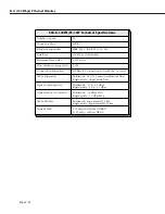
Page 86: ...ing simplifies the display of LEDs which are organized as a matrix see 32 Port Advanced Auto Sensing 10 100 Ethernet Switching Module on page 3 18 Software commands will number these ports 1 through 32 with Port A1 as 1 Port B1 as 9 C1 as 17 D1 as 25 etc The ESX K 100C 32W takes advantage of new Gigabit Ethernet Fast Ethernet ASIC technology known as Kodiak This module provides 4 priority levels a...

Page 87: ...uplex Maximum Frame Size 1 518 bytes MAC Addresses Supported ESX K 100C 32W 1 024 ESX K 100C 32W4 4 096 Connections Supported 10BaseT hub or device 100BaseTx hub or device Cable Supported 10BaseT Unshielded twisted pair UTP 100BaseTx Unshielded twisted pair Category 5 EIA TIA 568 Shielded twisted pair Category 5 100 ohm Maximum Cable Distance 100 m Current Draw 10 25 amps without an HRE X 11 75 am...

Page 88: ...ill blink Green when traffic is trans mitted or received on the port C C 1x 6x 2x 3x 4x 5x 7x 8x 1x 6x 2x 3x 4x 5x 7x 8x B B A A OK1 Hardware Status On Green when the module has passed diag nostic tests successfully On Amber when the hardware has failed diag nostics or if the corresponding image file for the module is not in flash memory OK2 Software Status Blinking Green when the module software ...

Page 89: ...timode connectors are black and single mode connectors are blue Note If your network currently uses SC connectors you can order MT RJ to SC cables from Alcatel The MT RJ fiber port supports full duplex operation You can configure half duplex mode on each port through 10 100cfg An additional software command 10 100vc allows you to view the current line speed and link mode of each port connection Th...

Page 90: ...upported 8 192 Connections Supported 100Base Fx connection to backbone or server Cable Supported Multimode 62 5 125 micron multimode fiber Single mode single mode fiber Optical output power Multimode 19 to 14 dBm Single mode 20 to 14 dBm Optical receiver sensitivity Multimode 31 dBm Max Single mode 31 dBm Max Cable Distance Multimode approximately 2 km Single mode approximately 15 km Current Draw ...

Page 91: ... 1 LASER PRODUCT 1 6 1 3 1 4 1 5 1 2 9 1 0 1 1 8 1 2 1 6 1 5 1 4 1 3 5 9 Each LED corresponds to a port on the module When an LED is on Green continuously a good cable connection exists The LED will blink Green when traffic is trans mitted or received on the port OK1 Hardware Status On Green when the module has passed diagnostic tests success fully On Red when the hardware has failed diagnostics O...

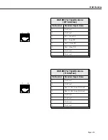
Page 92: ...htercard that attaches to an Omni Switch Router High Speed Module HSX The HSX contains RISC processors RAM for holding software image files ASICs for performing switching and Content Addressable Memory CAM for storing MAC addresses You plug your cable into the WSX submodule but it is the HSX module that connects to the switch s backplane WAN Pinouts The figures and tables on the following pages il...

Page 93: ...1 Not Used 2 Not Used 3 Rcv from TE 4 Rcv from TE 5 Xmt from TE 6 Xmt from TE 7 Not Used 8 Not Used 1 8 WAN BRI Port Specifications U Interface Pin Number Standard Signal Name 1 Not Used 2 Not Used 3 Xmt to Rcv from Network 4 Xmt to Rcv from Network 5 Not Used 6 Not Used 7 Not Used 8 Not Used 1 8 ...

Page 94: ...andard Signal Name 1 Rx_Ring 2 Rx_Tip 3 Chassis GND 4 Tx_Ring 5 Tx_Tip 6 Chassis GND 7 Chassis GND A jumper is provided for connecting Pins 7 and 8 to the chassis ground if required 8 Chassis GND A jumper is provided for connecting Pins 7 and 8 to the chassis ground if required 1 8 1 13 14 26 ...

Page 95: ...ck DTE XC A 24 DA A 24 TT A 17 XC B 11 DA B 11 TT B 35 Request To Send DTE RS A 4 CA A 4 RS A 7 RS B 19 CA B 19 RS B 25 Clear To Send DCE CS A 5 CB A 5 CS A 9 CS B 13 CB B 13 CS B 27 Data Set Ready DCE DR A 6 CC A 6 DM A 11 DR B 22 CC B 22 DM B 29 Data Terminal Ready DTE TR A 20 CD A 20 TR A 12 TR B 23 CD B 23 TR B 30 Data Carrier Detect DCE CD A 8 CF A 8 RR A 13 CD B 10 CF B 10 RR B 31 Local Loop...

Page 96: ... A Y DB 15 114 B AA Receive Clock DCE S A 6 115 A V DD 17 S B 13 115 B X Ext Transmit Clock DTE B A 7 113 A U DA 24 B B 14 113 W Request To Send DTE C A 3 105 C CA 4 C B 10 Clear To Send DCE 106 D CB 5 Data Set Ready DCE 107 E CC 6 Data Terminal Ready DTE 108 H CD 20 Data Carrier Detect DCE I A 5 109 F CF 8 I B 12 Local Loopback DTE 141 L LL 18 Remote Loopback DTE 140 N RL 21 Ring Indicator DCE 12...

Page 97: ... the WAN connec tion at the WSX S 2W board port or virtual circuit level Extensive statistics are provided at each level Software commands for Frame Relay are described in Chapter 29 Managing Frame Relay commands for PPP are described in Chapter 30 Point to Point Protocol With the optional HRE X you can increase routing performance to 1 5 million packets per second per module and up to 12 Mpps in ...

Page 98: ...s transmitting data RX Receive On half bright Green when idle and Green with occasional flickers when the corresponding port is receiving data Port LEDs O K 1 O K 2 OK1 Hardware Status On Green when the module has passed diagnostic tests success fully On Amber when the hardware has failed diagnos tics or if the corresponding image file for the module is not in flash memory OK2 Software Status Blin...

Page 99: ...cal DTE device It can be turned into a physical DCE device for speed or clocking purposes by plugging in a DCE cable The WSX SC board senses whether a DCE or DTE cable is connected Software in the switch allows you to configure parameters for the Frame Relay or Point to Point Protocol PPP Software commands allow you to view the status of the WAN connec tion at the WSX SC board port or virtual circ...

Page 100: ...sed using STAC 9705 Clocking Internal External or Split Virtual Circuits Supported Permanent Virtual Circuits PVCs MAC Addresses Supported 4 096 Connections Supported Physical Data Terminal Equipment DTE or Data Communication Equipment DCE Cable Supported DTE or DCE in the following types R2 232 V 35 X 21 RS 530 RS 449 Power Consumption WSX SC 4W without an HRE X 6 25 amps WSX SC 4W with an HRE X ...

Page 101: ...ing Mod ule on page 3 28 for further information on these LEDs Ports 1 through 4 Ports 5 through 8 WSX O K 1 O K 2 STA Status On Green con tinuously when the port con nection is operational Off when the port is disabled or the cable is detached Blink ing On Off if cable is attached but receive control data is detected as down This LED also blinks during initialization diagnostics or when invalid d...

Page 102: ...des an integrated CSU DSU to enable direct connection to a T1 E1 device such as a PBX or a T1 E1 line to a service provider You can configure physical port parameters through software commands Configuration options include frame format facility datalink and line coding In addition the switch can store up to 24 hours of local and remote statistics See Chapter 33 Managing T1 and E1 Ports for more in...

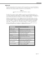
Page 103: ...l 56 64 128 256 384 512 768 1024 1536 1544 2048 Kbps Compression Hardware based using STAC 9705 Facility Datalink Protocol ANSI T1 403 and AT T 54016 MAC Addresses Supported 4 096 Connections Supported Physical Data Terminal Equipment DTE or Data Communication Equipment DCE Cable Supported Serial Ports DTE or DCE of the following types R2 232 V 35 X 21 RS 530 RS 449 Cable Distance T1 E1 short haul...

Page 104: ... port is transmitting or receiving data T1 E1 Port LEDs O K 1 O K 2 Module LEDs Please refer to 2 Port WAN Frame Relay Switching Mod ule on page 3 28 for further information on these LEDs S T A A L M A C T S T A T X R X 1 2 1 2 Port 1 T1 or E1 Port 2 Serial Port 3 T1 or E1 Port 4 Serial WSX STA Status On Green con tinuously when the port con nection is operational Off when the port is disabled or ...

Page 105: ...r of jumpers JP2 and JP4 on the back of the board to correspond to the type of cable you are using For more detailed information on the types of cables to use with this module see Appendix B Custom Cables The illustration below shows the correct jumper positions Note JP3 is reserved Do not set a jumper across JP3 Cable Termination Jumpers for WSX FE1 SC JP4 JP2 Coax Twisted Pair ...

Page 106: ...r a DCE or DTE cable is connected and configures itself appropriately The BRI port on the WSX BRI SC board can be configured as either a U or an S T type of interface the board is shipped set to U Either type of interface supports two B channels operating at 56 64 Kbps and one D channel operating at 16 Kbps Software running in the switch allows you to configure the operation of the Point to Point ...

Page 107: ...rted 4 096 Serial Port Connections Supported Physical Data Terminal Equipment DTE or Data Communication Equipment DCE Serial Cables Supported DTE or DCE in the following types R2 232 V 35 X 21 RS 530 RS 449 BRI Port Connections Supported U interface or S T interface jumper selectable U is shipping default Maximum Cable Distance BRI 100 m Switch Types Supported National ISDN 1 AT T 5ESS Northern Te...

Page 108: ...r S T 1 2 Module LEDs Please refer to 2 Port WAN Frame Relay Switching Mod ule on page 3 28 for further information on these LEDs 1 2 S T A R X T X U I F A C T S T A 1 2 Port 3 Serial Port Port 4 BRI Port U or S T WSX O K 1 O K 2 STA Status On Green con tinuously when the port con nection is operational Off when the port is disabled or the cable is detached Blink ing On Off if cable is attached bu...

Page 109: ...trans mit and receive termination for the S T interface The small labels next to the jumper pins at J13 J14 and J16 indicate which pins must be bridged to set the BRI port to either the U or the S T interface Part Number and Serial Number label this is how the board is shipped J16 S U S U J15 TT TT RT RT J14 S U S U J13 S U BRI Port Jumper Configuration for the S T Interface transmit receive termi...

Page 110: ...WAN Modules Page 3 40 ...

Page 111: ...Overview of Command Interfaces The Alcatel Omni Switch Router has two different command interfaces available for configur ing parameters and viewing statistics They are the User Interface UI and the Command Line Interface CLI Prior to software Release 4 4 the switch automatically booted up in the UI mode In Release 4 4 and later the Omni Switch Router is factory configured to boot up in the CLI mo...

Page 112: ...uses the switch to leave the CLI mode and enter the UI mode provided you are using a login with Read Write privileges You can verify that you are in the UI mode by typing to display the top level menu for the UI as shown below Command Main Menu File Manage system files Summary Display summary info for VLANs bridge interfaces etc VLAN VLAN management Networking Configure view network parameters suc...

Page 113: ...ype either quit or logout at the prompt then press Enter Your session is immediately terminated Note If you forget which command interface mode you are in type the character If you are in the UI mode the Main Menu will display as shown above If you are in the CLI mode the switch will show the following display NO SHOW VOICE SYSTEM ACCOUNTING ...

Page 114: ...ion management family to which the commands belong Hardware Commands The hardware section of this manual set consists of Chapters 1 through 3 There are relatively few UI commands in this section because these chapters cover the hardware elements of the switch The commands defined in these chapters are listed in the Hardware Table beginning on page 4 4 Basic Switch Management Commands The table beg...

Page 115: ... secondary mpm file replace secondary mpm file remove secondary mpm file store secondary mpm file takeover reload secondary mpm slip view secondary mpm file swap configuration auto copy takeover GF File 7 Managing Files cd cp load newfs ftp ls pwd rm imgcl cd copy load newfs ftp ls password rm imgcl GF CD GF System GF System GF System GF FTP GF LS 18 User GF RM GF System 8 Switch Security pw reboo...

Page 116: ...yscfg systat Unsupported No PM Support 10 Switch Logging secdefine secapply caplog cmdlog syslog conlog debuglog swlogc secure access filter secure access no filter view secure access filter security security custom security no custom Unsupported GF System 11 Health Statistics hdcfg health hmstat hpstat hreset health threshold view health statistics view health statistics view health statistics he...

Page 117: ...ic agg no view interface fastethernet interface ethernet GF Interface 16 Managing 802 1Q Groups cas das mas vas All commands used to create delete modify and view a service plus the message command are supported GF System 17 Configuring Bridging Parameters fddi fsmt fsid fsmtc fsstatus fmac fmaddr fmstats fmctrs fport fportstatus fportctrs fportc macstat slipc maccirstat selgp srsf srtbcfg srtbclr...

Page 118: ...num interface fddi svc group 802 1q atm service group elan group group num no 802 1q group no elan group mobility group mobility view group group router vlan router port mapping ingress no port mapping port mapping view port mapping port monitor configuration port monitor view port monitor resume port monitor group priority num view group priority no group group no interface view group auto view g...

Page 119: ...ulticast vlan port multicast vlan mac vlan protocol vlan binding ip vlan binding mac vlan binding port multicast vlan descr vlan default view group mac view group authenticated group mobility group authentication group authentication protocol view multicast vlan group mac group mac range group user group port group dhcp port group dhcp mac group dhcp range group protocol group binding ip group pro...

Page 120: ...ac ipr ips names ping probes ripflush rips risr snmpc snmps telnet tcpc tcps traceroute udpl udps xlat chngmac flush flconfig ipclass ipdirbrcast names probes iproute view rmon events view icmp rip filter view mac view ip route view ip traffic ip no domain lookup ping view rmon probes ripflush rips no ip route snmp config snmp communi ty snmp trap broadcast snmp trap unicast snmp station view snmp...

Page 121: ...s FRF9 stac interface clock source clock rate lmi type intf type lmi t391 dte lmi n391 dte lmi n392 dte lmi n393 dte lmi n392 dce lmi n393 dce 10 WAN 30 Point to Point Protocol PPP pppglobal pppadd pppmodify ppp global authentication ppp global sent username ppp global compress ppp global bridging status ppp global ip config admin status ppp global ipx status interface encapsulation ppp descriptio...

Page 122: ...rrier delay timeout max retries retry delay failure delay phone number speed caller id 10 WAN 32 Managing ISDN Ports isdnm interface bri switch type spid1 phone 1 spid2 phone2 10 WAN 33 Managing T1 and E1 Ports temod teccfg tecfg tebcfg channel group description framing cablelength linecode fdl clock source loopback signalmode snmp trap link status yellow send code non facility signaling bert patt...

Page 123: ... and Appendices A and B Troubleshooting Diagnostics Table Chapter Appendices UI Command Equivalent CLI Commands PM Family 35 Troubleshoot ing uic Unsupported No PM Support 36 Running Hardware Diagnostics diag Unsupported No PM Support A Boot Line Prompt ethernetc ethernet manager port No PM Support B Custom Cables No UI commands in this Appendix No CLI commands in this Appendix No PM Support ...

Page 124: ... network parameters such as routing etc Interface View or configure the physical interface parameters Security Configure system security parameters System View set system specific parameters1 Services View set service parameters Switch Enter Any to Any Switching menu Help Help on specific commands Diag Display diagnostic level commands Quit Logout Log out of this session Display the current menu c...

Page 125: ...g modules In addition it includes a sub option for configuring SLIP These sub menus are described in Chapters 15 through 16 and Chapter 29 Security This menu contains options for changing a password and rebooting the system It is described in Chapter 8 Switch Security System Contains a wide array of options for configuring and viewing information on a vari ety of switch functions Options include d...

Page 126: ...X Vision s on line help The Command Line Interface CLI The CLI is a new feature included with Release 4 1 that allows you to configure Omni Switch Routers using single line text based commands that are entered through the local console Improved readability easy text editing of the config uration files and simple cloning of switch configurations are among some of the advan tages of the CLI For more...

Page 127: ...en will stop and allow you to read the data Press Ctrl q to continue the data transmission The UI Configuration Menu The User Interface UI Configuration menu consolidates the following UI commands into a single easy to use menu chpr more ver ter timeout Note The switch s prompt more verbose terse and timeout functions remain fully supported However if you enter any of the commands listed above you...

Page 128: ...stem prompt display the system name You can also mix variables and literals such as Menu Path or SysName Enter command Note The default system prompt is To change the system prompt type uic at the user prompt and press Enter A screen similar to the following will be displayed UI Configuration 1 Prompt Menu Path 2 More on 21 Lines 22 lines 3 Verbose off 4 Timeout 5 minutes Command Item Value Help Q...

Page 129: ...ode is now set to on UI Configuration 1 Prompt Menu Path 2 More on 21 Lines 22 lines 3 Verbose off 4 Timeout 5 minutes Command Item Value Help Quit Redraw Save Redraw The switch s default output display is 22 lines If you want to change this value type 21 followed by the maximum number of lines to be displayed and press Enter For example 21 50 After you press Enter the screen will be redrawn Note ...

Page 130: ...of lines to be displayed and press Enter The value may range from 0 to 2147483647 For example 21 2000 After you press Enter the screen will be redrawn Note that the output display value at line 21 of the uic submenu has been changed UI Configuration 1 Prompt Menu Path 2 More on 21 Lines 2000 lines 3 Verbose off 4 Timeout 5 minutes Command Item Value Help Quit Redraw Save Redraw Type save at the su...

Page 131: ...2 off at the submenu prompt and press Enter The screen will be redrawn Note that more mode is now set to off UI Configuration 1 Prompt Menu Path 2 More off 21 Lines 22 lines 3 Verbose off 4 Timeout 5 minutes Command Item Value Help Quit Redraw Save Redraw Type save at the submenu prompt and press Enter More mode is now disabled Reminder The switch s table filtering feature cannot be used when the ...

Page 132: ...ry VLAN Networking Interface Security System Services Help The switch s default verbose mode setting is off or disabled To enable verbose mode type uic at the user prompt and press Enter A screen similar to the following will be displayed UI Configuration 1 Prompt Menu Path 2 More on 21 Lines 22 lines 3 Verbose off 4 Timeout 5 minutes Command Item Value Help Quit Redraw Save Redraw Next type 3 on ...

Page 133: ...sable verbose mode type uic at the user prompt and press Enter A screen similar to the following will be displayed UI Configuration 1 Prompt Menu Path 2 More on 21 Lines 22 lines 3 Verbose on 4 Timeout 5 minutes Command Item Value Help Quit Redraw Save Redraw Next type 3 off at the submenu prompt and press Enter The screen will be redrawn Note that verbose mode is now set to off UI Configuration 1...

Page 134: ...tes Command Item Value Help Quit Redraw Save Redraw Next type 4 on followed by the desired automatic logout time and press Enter For exam ple 4 15 After you press Enter the screen will be redrawn Note that the automatic logout time at line 4 of the uic submenu has been changed UI Configuration 1 Prompt Menu Path 2 More on 21 Lines 22 lines 3 Verbose off 4 Timeout 15 minutes Command Item Value Help...

Page 135: ...en you enter a command for a menu or sub menu and the amount of information you receive when you run the help command Refer to Setting Verbose Terse Mode for the User Interface on page 4 22 for more information Additionally there is a lookup facility to assist with administrative tasks You can look up any command name or prefix as follows lookup vlans or to see all commands starting with v use loo...

Page 136: ...er of commands by entering history followed by a number less than or equal to the number of commands in the history buffer For example if you entered history 5 in the example above you would see the following 7 vivl 8 fwtvl 9 xlat 10 history 11 history 5 The UI also provides several other ways to re execute earlier commands For example you can re execute a specific command shown in the history lis...

Page 137: ...ntly executed command containing a string of charac ters by entering an exclamation point and a question mark followed by the string of characters and an optional question mark which acts as a wild card In the example at the beginning of this section entering lan at the system prompt would re execute the vlan command Entering la however would re execute the xlat command because it is the most rece...

Page 138: ...ystem interprets the abbreviated address As shown in the table above the system performs two important steps to ensure that the IP address is valid First it puts zeroes when you do not specify the number Second the system will insert as many zeroes as needed to the right of a period Abbreviated IP Address Formats Sample User Entry IP Address 198 0 0 0 198 198 198 0 0 0 198 198 0 0 0 198 198 0 0 0 ...

Page 139: ...tering ping 198 2 at the system prompt After you answer a few prompts see Chapter 25 IP Routing for more information on the ping command something similar to the following will be displayed Ping starting hit Enter to stop PING 198 0 0 2 64 data bytes 0 T 198 0 0 2 PING Statistics 1 packets transmitted 0 packets received 100 packet loss In addition the IP subnet mask 255 255 0 0 can be abbreviated ...

Page 140: ...hpr Change the prompt for the system obsolete use uic command logging View system logs health Set health parameters or view health statistics cli exit Enter command line interface saveconfig Dump the cache configuration content to the mpm cfg file cacheconfig Set the flag to use cache configuration only Main File Summary VLAN Networking Interface Security System Services Help For information on th...

Page 141: ...r will be displayed For example if you enter history at the system prompt it will not be displayed on your terminal as shown in the example below Setting the Login Banner The login banner feature allows you to change the banner that displays whenever someone logs into the UI This feature can be used to display messages about user authorization and security You can display the same message for all ...

Page 142: ...menu This command will cause the banner message to display at each login until the switch is rebooted After a reboot the switch will not display the banner unless the alert command is executed again Permanent Banner If you want the banner message to display after the system has been rebooted you must add additional lines to the mpx cmd file The following example lists the commands you must add to ...

Page 143: ... Releases 4 4 and later more than one login account with write privileges can be active at the same time For software Release 4 3 and earlier only one login account with write privileges was allowed on the switch at the same time In this case the first switch user who logged on as either admin or diag would be the only user with the write privilege Subsequent users who logged on as either admin or...

Page 144: ...fffd 00000000007fffff pty telnetA 123 456 78 910 The following sections describe the parameters shown by the who command SESSION The session number of the user A 0 indicates that the user is connected through the console port a 1 indicates that the user is connected through the modem port and a 2 or 3 indicates that the user is connected through Telnet The session number is used with the write and...

Page 145: ...tch would display ERROR Session 1 is an invalid session number Note After you have received a message or after you have written a message you must press the Enter key to regain the system prompt Deleting Other Sessions If you are logged on as admin or diag you can kill the session of another user For example if you want the write privilege and you are logged on as diag or admin you must end the se...

Page 146: ... If the user who was logged off had the write privilege you will gain the write privilege and a message similar to the following will be displayed Done You have gained the WRITE privilege You can use the who command to confirm that you now have the write privilege In addition the session number used in the kill command must be valid If for example you entered kill 1 and no user was connected to th...

Page 147: ...ourself If you wanted to kill the session of the user with a session number of 2 immediately you would enter kill f 2 at the system prompt The default timeout for the kill command is 2 seconds You can modify the duration of the timeout by using t option in conjunction with the f option To use the timeout option enter kill followed by t the number of seconds for the timeout f and the session number...

Page 148: ...rch and Filter commands cannot be used For more information on the more command see The UI Configuration Menu on page 4 17 A typical More UI prompt will look like this At the More prompt the user is given a list of options which includes the Search and Filter F commands SP Press SP space bar to display the next page of information CR Press CR character return to display the next line of informatio...

Page 149: ...owing will be displayed Note that because the information in the table exceeds the more command s default page size of 22 lines the More prompt appears at the bottom of the screen Total number of MAC addresses learned for this slot 58 Non Canonical Group CAM Last Exp Sl If Service In MAC Address MAC Address T ID Indx S Seen Timer 3 1 Brg 1 00A0C9 064D04 000593 60B220 E 1 7024 T 134 300 3 1 Brg 1 0...

Page 150: ... the maximum number of table entries designated by the more command you can renew the Search Do this by typing n at the More prompt The Search command will scan the remainder of the table and display the next line containing the desired text pattern at the top of the screen Searching 3 1 Brg 1 0020DA 9E479D 00045B 79E2B9 E 1 702C T 138 300 3 1 Brg 1 0020DA 9D0D1B 00045B B9B0D8 E 1 7030 T 67 300 3 ...

Page 151: ...ern exactly as it would appear in the UI table Real World Example The following example uses the Filter command to display only those lines containing Lane services in the vivl table Before using this example be sure that the more mode is enabled and the default is set at 22 lines For more information refer to page 4 38 1 Type vivl and press Enter A table similar to the following will be displayed...

Page 152: ...and To further refine your results you can combine the Search and Filter commands To combine the Search and Filter commands type at the Filter mode s More prompt followed by a revised text pattern of up to 80 characters Note that you can combine the Search and Filter commands only after you have executed a Filter command and received a More prompt at the bottom of the resulting page Reminder Both ...

Page 153: ...5 0 0 172 37 4 33 1 33 7 DIRECT 172 111 0 0 255 255 0 0 172 111 4 33 1 111 1 DIRECT 198 168 12 0 255 255 0 0 192 168 12 1 1 1 1 DIRECT 198 168 13 0 255 255 0 0 192 168 13 1 1 1 1 DIRECT More SP CR F N Q Filtering 198 168 12 0 255 255 0 0 198 168 12 1 1 1 1 DIRECT 198 168 13 0 255 255 0 0 198 168 13 1 1 1 1 DIRECT 198 168 236 0 255 255 0 0 172 16 255 254 4 1 1 DIRECT 198 168 237 0 255 255 0 0 172 1...

Page 154: ...commands Any number of wildcards can be used within a single search string In addition multiple char acter and single character wildcards can be combined within a single search string Wildcard Command Options Multiple Characters An asterisk is used as a wildcard for multiple characters in a text pattern For example the Filter pattern img will filter out all lines from the UI table except those con...

Page 155: ...g 127 followed by any single character and then the remaining text pattern 0 1 For example 127 0 0 1 Note If you use a wildcard at the Search command and the resulting page still exceeds the maximum number of table entries designated by the more command you can renew the search starting from the next line contain ing the text pattern Do this by typing n at the More prompt Note that you can renew a...

Page 156: ...UI Table Filtering Using Search and Filter Commands Page 4 46 ...

Page 157: ...minal emula tor that supports the ZMODEM protocol You can do this using the file commands in the User Interface or through the boot line prompt Note that a ZMODEM transfer of larger files can take several minutes to complete Do Not Mix Software Versions When loading software ensure that the versions of software for all the modules are from the same release Mixing earlier versions of software with ...

Page 158: ... be able to see the files contained in the flash directory It is the only directory in the switch 3 Note that because of the organization of files in the switch any time a file is deleted the flash memory is compacted Depending on the number of files in the switch and where they are located in memory this compaction can take anywhere from a few seconds to a couple of minutes 4 When you transfer a ...

Page 159: ...hash ls put pwd quit remotehelp user lpwd ascii Set transfer type to ASCII 7 bit binary Set transfer type to binary 8 bit bye Close gracefully cd Change to a new directory on the remote machine delete Delete a file on the remote machine dir Obtain a long listing on the remote machine get Retrieve a file from the remote machine hash Print the hash symbol for every block of data transferred This com...

Page 160: ... recommended that you run it at 38 4 Kbps Running at 19200 is twice as fast as 9600 To set the baud rate use the ser command For more information on the ser command see Chapter 6 Configuring Management Processor Modules Note If a file you are transferring already exists in the switch s flash memory you must remove the file before transferring the new file via ZMODEM Using ZMODEM with the load Comm...

Page 161: ... to the console port The terminal must be set to the last values set in the switch before it was powered down For example if you were running at 19200 8 n 1 you must set your terminal to these values Note If you have deleted or lost your configuration file mpm cfg the console port values will revert back to the factory settings which are 9600 8 n 1 If you are not sure what baud rate your switch is...

Page 162: ...L list ffs files P Purge system remove ALL ffs files R file files remove ffs file s S save boot configuration V display bootstrap version dev 0 procnum host file h e b g u usr pwr passwd f tn targetname s script o other Boot flags 0x02 load local system symbols 0x04 don t autoboot 0x08 quick autoboot no countdown 0x20 disable login security 0x40 use bootp to get boot parameters 0x80 use tftp to ge...

Page 163: ...rompt Type in the at command to load the boot parameters Boot Boot device zm Boot file flash mpx img Startup script flash mpx cmd Console params 9600 n8lc Modem params 9600 n8l Boot flags 0xb Other dvip no_name 198 206 183 253 255 255 255 0 198 206 183 255 Attaching network interface lo0 done Disk load or Boot load D B Q d 4 At the Disk load or Boot load D B Q prompt type in d to tell the system t...

Page 164: ...Using ZMODEM Page 5 8 ...

Page 165: ... commands described in this chapter also work with the Omni Switch Router MPX The Omni Switch Router also support two MPXs with one acting as the primary and with one acting as the secondary If the primary MPX fails the secondary MPX can take over automati cally Operating with redundant MPXs can also help avoid network downtime Note When you have two MPXs in one chassis they must be installed in s...

Page 166: ...s the Console Port C 4 The current port values are shown followed by a prompt to change the speed value Current Console DCE configuration 9600 bps 8 data bits None parity 1 stop bit running Console shell Speed 9600 Enter the speed in bits per second at which you want the port to operate or simply press Enter to accept the default in parentheses Valid values are 1200 9600 19200 and 38400 bps 5 The ...

Page 167: ...t reaches the highest speed 38400 bps it toggles back to the lowest speed 1200 bps You cycle through the port speeds in the following order 9600 19200 38400 1200 Note On the MPX you must remove the default baud rate shunt E1 which fixes the baud rate at 9600 bps before you can change the baud rate This shunt is located near the front end of the circuit board just to the right of the Ethernet manag...

Page 168: ...to access switch software through the console port A fourth valid configuration that keeps both ports active is modem port mode auxiliary console port mode console This configuration allow you to use the console and modem ports simultaneously to access switch software Configuring SLIP To configure SLIP enter the slipc command If you enter the command and SLIP is not running on any ports the system...

Page 169: ...r mation on using this command The Redraw option refreshes the screen You make changes by entering the line number for the option you want to change an equal sign and then the value for the new parameter When you are done entering all new values type save at the colon prompt and all new parameters will be saved If you do not want to save the changes enter quit or Ctrl D Important Note On some revi...

Page 170: ...t address is automatically derived from the default VLAN IP address class the default is 192 255 255 255 You can enter a new address in dotted decimal or hexadeci mal notation For example to change the broadcast address to 198 206 184 255 enter 4 198 206 184 255 at the prompt 5 Gateway Address You can enter an IP address for the first hop router to a remote host if the host is on a differ ent IP n...

Page 171: ...nchronization on page 6 15 for more information on the syncctl command 2 If automatic file synchronization is already disabled simply press Enter If it is enabled enter disable at the prompt 3 Enter ethernetc at the prompt See Configuring the Ethernet Management Port on page 6 5 for more information on the ethernetc command 4 Enter 2 followed by the IP address for the EMP on the primary management...

Page 172: ... Ports and Redundant Management Processor Modules Page 6 8 12 Enter save at the prompt to save the IP address 13 Enter renounce at the prompt to make the management module that was originally the primary one primary again ...

Page 173: ...his slot 2 holds the secondary MPM MPM Menu Commands The mpm command also takes you to the mpm menu which contains the commands needed to configure single and redundant MPXs With a serial or modem connection you can communicate with either the primary or secondary MPX by connecting to the respective RS232 connectors With a telnet connection however you can only communicate with the primary MPX Typ...

Page 174: ...ash directory you want to use when you access a secondary MPX from a primary MPX and when you access a primary MPX from a secondary MPX All of these commands begin with the prefix mpm and are listed below mpmstore mpmreplace mpmload mpmrm mpmget To indicate which flash directory you want to use enter a slash the name of the direc tory and another slash before the file name in all commands that beg...

Page 175: ...pe of file which includes configuration cnf and cfg command cmd and image img The image file suffix can be changed for both the primary and secondary MPXs with the nisuf command which is described in Setting the Load Suffix on page 6 14 Transferring a File to the Secondary MPX The mpmstore command transfers a file in the flash memory of the primary MPX to the flash memory of the secondary MPX To u...

Page 176: ...lace flash mpm log at the system prompt The following will be displayed Deleting Transferring If the file already exists on the target MPX and it is identical to the one you are transferring something similar to the following message File mpm log is identical on Primary and Secondary 2 If the files are identical the mpmreplace command will terminate and the file will not be replaced Loading a File...

Page 177: ...the mpmrm command You cannot use wildcards to remove multi ple files For example to remove the file mpm log from the flash directory on the secondary MPX in slot 2 for example you would enter mpmrm flash mpm log at the system prompt Something similar to the following will be displayed Checking for flash mpm log on slot 2 After a brief moment the file will be deleted from the secondary MPX and some...

Page 178: ...eset after displaying the following message System going down immediately The switch will reboot and the original secondary MPX will be the primary once the switch comes back up Setting the Load Suffix The nisuf command sets the load suffix for the switch s executable image files The factory default suffix is img Warning The nisuf command should only be used when it is necessary to have two versio...

Page 179: ...synchronization is now Enabled Note that automatic configuration synchronization is disabled unless all image img and Programmable Gate Array PGA files in the switch are synchronized first See Synchronizing Image Files on page 6 16 for information on the imgsync command which synchronizes image and PGA files The interval between updates is 5 minutes The primary MPX will copy any changes to the sec...

Page 180: ... in sync i e have the same configuration To synchronize all the image files enter imgsync at the system prompt When you run imgsync you will be asked if you want to synchronize the cmd file and or PGA files if they are found to be different Note If any PGA file is being used by a Token Ring module and you choose to sync the cmd file then the PGA file that is in use will be synced even if you do no...

Page 181: ...To use this command enter mpmget followed by a space a slash the name of the flash directory another slash and the name of the file you want to transfer For example to load the file mpm log from the flash directory on the primary MPX to the secondary MPX you would enter mpmget flash mpm log at the system prompt After a brief moment the file will be transferred into the secondary MPX The following ...

Page 182: ...mand should only be used during network down times since it could cause network inter ruptions To transfer control from primary MPX to the secondary MPX enter takeover at the system prompt The following prompt will display Confirm n Press y to transfer control to the secondary MPX or press n to cancel the command the default is n If you enter y the switch will reset after displaying the messages s...

Page 183: ... off power to the module the MPX will be in the same state after a reset as it is after a power on To reset a secondary MPX enter secreset at the system prompt Messages similar to the following will display Module 1 changed while Swap OFF Syncing configuration data with secondary 1 complete Note To reset a switching module use the reset command which is described in Chapter 36 Running Hardware Dia...

Page 184: ...led ON to hot swap a switching module If not the system may halt or restart See the subsection below for instructions on enabling the swap mode Enabling the Swap Mode To turn the swap mode ON enter swap on at the system prompt The default for swap mode is 5 minutes Something similar to the following will be displayed Swap is ON for 5 minutes When you turn the swap state on you set a timer which de...

Page 185: ...can manually turn the swap mode off This function is particularly useful since the perfor mance of the switch can be adversely affected if the swap mode is enabled To turn the swap mode off immediately enter swap off at the system prompt The swap mode will be disabled and something similar to the follow ing will be displayed Swap is OFF timeout is 5 minutes ...

Page 186: ...Displaying and Setting the Swap State Page 6 22 ...

Page 187: ...s commands for loading listing copying and deleting individual switch files To access the File menu enter file at the UI prompt If verbose mode is enabled the following list of commands will be displayed automatically If verbose mode is disabled press the question mark to display the following list of commands For information on enabling verbose mode refer to the uic command descrip tion in Chapte...

Page 188: ... in flash memory during the boot process you do not have to load them Important If you remove the configuration files mpm cnf and mpm cfg from your switch all of your switch s non default configuration settings will be deleted at the next boot sequence Use caution when removing configura tion files and be sure to create backup copies if you want to safeguard your current configuration Changing Dir...

Page 189: ... bytes free The ls command lists all the files in the current working directory of the primary MPX s flash memory followed by its size in bytes creation date and creation time The three letter file extension indicates the type of file Examples include configuration cnf and cfg command cmd image img Programmable Gate Array pga etc The ls command also lists the total number of bytes of free memory i...

Page 190: ...ltiple file names be sure to include a space between each file name you want to delete For example to remove both the mpm cfg and mpm cnf files you would enter the following rm mpm cfg mpm cnf Wildcards let you substitute an asterisk for file name text You can remove all files with the same extension by entering rm followed by an asterisk a period and the file extension For example if you want to ...

Page 191: ...system prompt A screen similar to the one shown below will be displayed Remove the following flash esx img flash mpx img Are you sure you want to remove them n Press the y key to delete all the image files or press Enter to cancel If you press the y key the switch will spend several minutes deleting the image files Note If you want to delete all files in flash memory you can use the newfs command ...

Page 192: ...ak 100 Displaying Text Files You can use the view command to display the contents of ASCII text based files To use this command enter view followed by the name of the file you want to display To display the mpx cmd file for example enter view mpx cmd at the system prompt A screen similar to the one shown below will be displayed cmDoDump 1 cmInit Note that if you try to view a file with non ASCII c...

Page 193: ...ne from the buffer eb Edit a buffer line ib Insert buffer line lb List contents of the buffer nb Name file for buffer rb Read file into buffer wb Write buffer to file Main File Summary VLAN Networking Interface Security System Services Help The Edit sub menu commands are outlined in the following sections You can edit up to 100 lines of text Each line of text can be up to 97 characters long Note W...

Page 194: ...cal example 00 cmDoDump 1 01 cmInit If there is nothing in the buffer nothing will be displayed Adding Lines of Text to the Text Buffer You can use the ab command to manually add lines of text to the Edit sub menu Note that the lines you enter are appended at the end of the buffer For example if there are 10 lines of text in the buffer you will begin entering text at the 11th line If the buffer is...

Page 195: ...add the text atm_use_mbus 3 between lines 00 and 01 in the buffer enter ib 1 at the system prompt The following screen will be displayed 01 Enter the line of text atm_use_mbus 3 At the system prompt enter the lb command to view the contents of the buffer If the origi nal text buffer looked like this 00 cmDoDump 1 01 cmInit the revised text buffer with the inserted text will now appear as follows 0...

Page 196: ...or write a text file from the text buffer To use this command enter wb followed by the name of the output file For example if you want to create the file switch txt enter wb switch txt at the system prompt The following screen is displayed Work buffer name is flash switch txt Writing Changes to Existing Files You can also use the wb command to overwrite changes to an existing file For example if y...

Page 197: ...e actual multi command procedures that you may encounter as you work with your switch Real World Example 1 cp mpx cmd mpx bak rb mpx cmd lb 00 cmDoDump 1 01 cmInit nb mpx cmd Work buffer name is flash mpx cmd ab 02 02 reg_port_rule 1 03 No line 3 inserted lb 00 cmDoDump 1 01 cmInit 02 reg_port_rule 1 Work buffer name is flash mpx cmd wb flash mpx cmd exists in flash Overwrite it y File system comp...

Page 198: ...t_rule 1 nb mpx cmd Work buffer name is flash mpx cmd db 2 lb 00 cmDoDump 1 01 cmInit ib 1 01 01 rifStripping 1 lb 00 cmDoDump 1 01 rifStripping 1 02 cmInit Work buffer name is flash mpx cmd wb flash mpx cmd exists in flash Overwrite it y File system compaction in progress view mpx cmd cmDoDump 1 cmInit rifStripping 1 ...

Page 199: ...d to system power and environment taskstat View task utilization stats memstat View memory use statistics fsck Perform a file system check on the flash file system newfs Erase all file from flash and create a new file system syscfg Configure info related to this system uic UI configuration change prompt timeout more verbose camstat View CAM info and usage camcfg Configure CAM info and usage hrex E...

Page 200: ...forming a file system check using manual mode If a file is encountered with a potential problem you may wish to consider preserving it for technical support analysis Flash file system check in progress Checking root file system OK Performing file consistency check Done There doesn t appear to be a system problem related to the Flash File system or kernel file system data structures If you are expe...

Page 201: ...flash file system you might want to use the fsck command to help determine where problems may exist Are you absolutely sure you want to strip the current file system and create a new one n Press Enter to cancel or enter y to create a new file system If you enter y you will have to load new software into the switch Warning Do not power down the switch after running the newfs command until you reloa...

Page 202: ...Creating a New File System Page 7 16 ...

Page 203: ...clog Display Secure Access log file entries secdefine Define Secure Access filter s secapply Apply Secure Access filter s useradd Create a new user for a login account usermod Modify a user s privileges userdel Remove a user asacfg Configure Authenticated Switch Access userview View the users in the local user database auth Enter the Authentication menu Main File Summary VLAN Networking Interface ...

Page 204: ...echo display the password char acters 1 From the prompt type pw account name The account name is the user login name diag admin for which you want to change the password The following prompt displays Changing password for account account name Old password 2 Enter the old password and press Enter If you enter the old password incorrectly the following message displays Authentication failure and the...

Page 205: ...nd will interrupt the network connections on the switching modules To reboot the switch from the command line enter reboot at the prompt and press Enter The following prompt will display Confirm n Enter Y The following message displays Locking file system locked System going down immediately switch 489917b0 System rebooted by admin The switch will now take at least a minute to start up again If yo...

Page 206: ... and the physical ports receiving data The following is a sample secdefine display Secure Access Filter Database List l Create c Delete d Modify m Find f Help h Quit q Enter selection Select an option by entering the relevant letter at the selection prompt To exit this menu enter q quit Descriptions and sample displays for each of the options are as follows List This is a list of all defined filte...

Page 207: ...witch only from this source MAC address If you leave this field blank a value of ANY will display in the secure access list allowing this user access to the switch from any MAC address Is this MAC in Canonical or Noncanonical C or N C The format of the specified MAC address Typically ethernet MAC addresses are in canonical format while token ring and addresses are in noncanonical format The defaul...

Page 208: ...articular field press Enter and the existing user information will remain unchanged To change a field to ANY privilege enter a value of 0 an asterisk or ANY at the prompt Descriptions of the fields in the above display are provided earlier under the option List on page 8 4 Find This option allows you to find information about a specified filter in the secured access data base You must know the fil...

Page 209: ...Value Help Quit Redraw Save Redraw Note If security is enabled for a filter point and there are no names defined on its list then the filter point is essen tially inaccessible to all users For example in the above sample display SNMP is not accessible to any user You can enter commands by entering just the first letter of the command For example select Quit by entering q and pressing Enter The que...

Page 210: ... is enabled for Trivial File Transfer Protocol on the switch Enabled means security is enabled for TFTP services and only users on TFTP s filter list are authorized Disabled indicates that security is not enabled for TFTP services and all users can access the switch through TFTP 5 HTTP Security Indicates whether or not security is enabled for HyperText Transfer Protocol HTTP on the switch Enabled ...

Page 211: ...le or disabled or d for disable at the prompt For example to enable security for Telnet enter the following 2 e Adding Filters To add a filter at the command prompt enter the line number for the parameter followed by an equal sign and then the filter s name at the prompt For example 21 Test Note If the filter does not exist in the secure access data base the system prompts you to create the filter...

Page 212: ... Intf secs 12 49 02 FTP 172 23 8 801 1 5 1 23 03 15 34 Telnet 198 20 2 101 10 2 3 240 Descriptions of the fields are as follows Time The first time the access violation occurred Protocol The IP protocol for which the violation occurred Source IP The source IP address of the unauthorized user Attempts The number of access attempts made by this user within the sample period 5 minutes Slot Intf The p...

Page 213: ...es A user account refers to the user s ability to log onto the switch and perform certain functions From the user s perspective it consists of the login name and a password A privilege refers to the user s ability or permission from the system administrator to execute a command Partition Management Requirements Partition management is available only for user login accounts that have no permission ...

Page 214: ...dding a User Account Using the UI Command Mode To add a user account you must be logged into an account with administrative privileges 1 At the system prompt enter the useradd command The following prompt displays Enter Username 2 Enter the desired user name The following prompt displays Force Password change on next login y n y 3 Press Enter to force a password change at the next login for this u...

Page 215: ...re limited to 16 text characters The new login account and password will take effect at the user s next login session Assigning Account Privileges Using the CLI Command Mode A user account s READ and WRITE privileges can be assigned for all commands or for various subsets of commands The command subsets referred to as command families are shown here config vlan iprout ipxrout bridge snmp xswitch h...

Page 216: ...ount for which you want to assign READ ONLY privileges The list of families parameter indicates the switch command families and the specific commands for which the user account will receive READ ONLY privi leges For a list of command families and specific commands refer to the Assigning Account Privileges Using the UI Command Mode section on page 8 16 or to Adding a User Account Using the CLI Comm...

Page 217: ...r login account name and user password is the new user password Both these values are defined by the user To set or change the password of the current user account use the following command password password Where password is the new password for this user account To delete a login account use the following command no user user_name where user_name is the current login you want to delete To view u...

Page 218: ... login name of the user account you are modifying The following screen will display CONFIG NO GROUP NO IPROUT NO IPXROUT NO BRIDGE NO SNMP NO XSWITCH NO HREFILTER NO ATMSER NO ATMUP NO CEM NO CSM NO PNNI NO ATMACCT NO VOIP NO MPOA NO MPLS NO USER NO Subsets of the global family SYSTEM NO STATUS NO SLOT NO TIMEOUT NO PROMPT NO DEFINE NO PREFIX NO REBOOT NO TELNET NO FTP NO PING NO SWAP NO RESET NO ...

Page 219: ...ich you want to set WRITE privileges Refer to the Command Family Table on page 8 18 for the number For example if you wanted to enable WRITE privileges for the Bridge command family enter the number 5 as shown here Give the family number 5 The following will display Give rights on family BRIDGE 0 NO 1 READ 2 WRITE 3 READ WRITE Enter the number 2 at the prompt to assign WRITE privileges The followi...

Page 220: ...8 SET ALL GLOBAL SUBSET 1 TO 8 c ancel or s save To give the user account the privilege to set all global commands enter the numeral 8 To deny the user the privilege to set any of the global commands enter the numeral 7 To set individual global commands enter the number 6 If you are assigning privileges on an indi vidual command basis the display will look like this 1 TO 8 c ancel or s sav 6 Give ...

Page 221: ...e user account privileges the switch displays the current configuration At this point you may enter s to save your configuration or c to cancel Warning If partition management is implemented on a user account that account must have the UI command family set to NO privilege If an account has the privi lege to use the UI command partition management is effectively destroyed for that account Global F...

Page 222: ...itions of the privileges 3 Enter the number for the privilege you want to add or remove The entry acts as a toggle to turn the privilege on or off for the user In the current example if you enter 2 at the prompt a screen similar to the following displays User TechPubs1 is configured with the following privileges READ WRITE 4 After modifying the privileges for the user enter s at the selection prom...

Page 223: ... Support on page 9 30 multicast claiming described in Multicast Claiming on page 9 32 disabling flood limits described in Disabling Flood Limits on page 9 32 and saving configurations described in Saving Configurations on page 9 33 Summary Menu The Summary menu consists of commands for displaying summary switch information To access this menu enter summary at the UI prompt Type the question mark t...

Page 224: ...field is set by the syscfg command which is described in Configur ing System Information on page 9 23 System Object ID The MIB entry for the switch where the object ID starts This is read only This value helps you locate Alcatel specific variables in the MIB tree Agent Up Time The time in days hours minutes and seconds since the switch was re initial ized Contact The name of a person to contact ab...

Page 225: ...vice Chassis ID The chassis ID for this switch Description The description of this chassis This field is set by the syscfg command which is described in Configuring System Information on page 9 23 Backplane The style of backplane in this chassis Master MPM Serial No The serial number for the primary MPX Physical Changes The number of physical changes that has occurred since the last reset or power...

Page 226: ...Router Enabled Active 4 SoftwareLoopback Enabled Enabled The fields displayed by the si command are described below Logical Interface A number in sequence that has been assigned to the virtual router port Interface Type The type of interface which can be virtual router the standard interface type SLIP and software loopback Administrative Status Whether the administrator has enabled or disabled the...

Page 227: ... X management command sub menu ver ter Enables disables automatic display of menus on entry obsolete echo noecho Enable disable character echo chpr Change the prompt for the system obsolete use uic command logging View system logs health Set health parameters or view health statistics cli Enter command line interface saveconfig Dump the cache configuration content to the mpm cnf file cacheconfig S...

Page 228: ...on Cold Start Load go Action on Reset Restart VBus Mode Mode 1 Script File flash mpx cmd Boot File flash mpx img Ni Image Suffix img The fields displayed by the info command are described below System Make The description of the specific type of chassis or device System Type The OmniSwitch type Description A description of the chassis and product This field is set by the syscfg command which is de...

Page 229: ...tic configuration synchronization System Base MAC Address The base MAC address for the primary MPX in chassis Number of Free Slots The number of slots not occupied by a module Action on Cold Start The action taken when you switch the power on Action on Reset The action taken when you reboot Script File The name of the command file mpx cmd is the default containing user config urable commands Boot ...

Page 230: ... date you would enter 2 4 20 99 After you have made changes enter save to save your changes and to exit the dt menu If you do not wish to make any changes enter quit at the system prompt The following sections describe the variables on this screen 1 Local time Indicates the current and local time To set the time enter the line number for Local Time 1 followed by the new time The time format is as ...

Page 231: ...name There is a limited number of time zone names available For example if the local time zone name is Moun tain Standard Time MST you would enter 3 MST This specification automatically sets the switch to 7 hours the number of hours MST is offset from UTC Daylight Savings Time The software will automatically configure DST values for a specified time zone However the user can manually modify DST va...

Page 232: ... No default ZP8 China Manila Philippines 8 00 No default No default No default ZP7 Bangkok 7 00 No default No default No default ZP6 No standard name 6 00 No default No default No default ZP5 No standard name 5 00 No default No default No default ZP4 No standard name 4 00 No default No default No default MSK Moscow 3 00 Last Sunday in March at 2 00 a m Last Sunday in Oct at 3 00 a m 1 00 EET Easte...

Page 233: ...ard Time 4 00 1st Sunday in April at 2 00 a m Last Sunday in Oct at 2 00 a m 1 00 EST Eastern Stan dard Time 5 00 1st Sunday in April at 2 00 a m Last Sunday in Oct at 2 00 a m 1 00 CST Central Stan dard Time 6 00 1st Sunday in April at 2 00 a m Last Sunday in Oct at 2 00 a m 1 00 MST Mountain Standard Time 7 00 1st Sunday in April at 2 00 a m Last Sunday in Oct at 2 00 a m 1 00 PST Pacific Stan d...

Page 234: ...e line number for DST Start Week 42 and the week as follows 42 3 43 DST Start Day Indicates which day of the week DST starts To set the day DST should start enter the sequen tial number of the day Sunday 1 Monday 2 Saturday 7 For example if you want DST to begin on Friday you would enter the line number for DST Start Day 43 and the day as follows 43 6 44 DST Start Time Indicates what time of day i...

Page 235: ...mber for DST End Day 47 and the day as follows 47 4 48 DST End Time Indicates what time of day in local time DST ends To set the time DST should end enter the time in the form of HH MM where HH is the clock hours of a 24 hour military clock and MM is the clock minutes that DST should end For example if you want DST to end at 2 00 a m you would enter the line number for DST End Time 48 and the time...

Page 236: ...30 3 1 ATM B 53404116 01 11 01 05004400 4 Ether 8 Enabled D 53404229 01 07 01 4 3 05000014 Operational 00 20 da 03 09 90 5 F Ether M Enabled A5 73250839 01 07 01 4 3 05015906 Operational 00 20 da 85 40 50 The fields display by the slot command are described below Slot The slot number for the MPX or switching module Module Type The type of module in this slot Part Number The factory assigned part n...

Page 237: ... occurs or when the switch is first powered up and many unknown MAC frames are being forwarded to the MPX MPM total memory The amount of total memory installed on the MPX MPM Free Memory The amount of free or unused memory available in the MPX This data is also displayed by the memstat command which is described in Viewing MPX Memory Statis tics on page 9 20 MPM CPU Utilization 5 seconds The amoun...

Page 238: ...er as shown here clearstat 3 This entry will clear all statistics for the module located in slot 3 If you want to clear statistics for a specific port service or instance enter the clearstat command followed by the appropri ate numbers You must use a comma to separate the slot number from the port service and instance numbers The following command will clear all statistics for port 1 of the module...

Page 239: ...ks in descending order in terms of the switch s CPU utilization You may use the taskstat 0 command if you want to list utilization statistics for all the tasks executed by the switch The taskshow command displays a table listing all tasks and their priority status and memory allocation A partial table is shown here NAME ENTRY TID PRI STATUS PC SP ERRNO DELAY tExcTask _excTask 499f7f20 0 PEND 48920...

Page 240: ...urrent status of the specified task PC Program Counter The program counter identifies the routing code as it enters the stack SP Stack pointer The stack pointer points to the code being loaded when the status is taken ERRNO Error number indicator DELAY The time elapsed between task routines ...

Page 241: ...cti 2 Functi 3 Address Len Time 49a69a58 tUi_she 484fe4do 484f1284 484ffbc8 4800ef28 9 TUE APR 24 18 06 4 7 2001 49559bb8 t_AtmMg 49db6e90 49d6a780 49d4c3bd 4800ef88 16 TUE APR 24 18 06 4 6 2001 49559bb8 t_AtmMg 49db6e90 49d4be4c 49d8639c 4800efb8 64 TUE APR 24 18 06 4 6 2001 49559bb8 tUi_she 49db6e90 49d9cce4 49d9c910 4800f050 4 TUE APR 24 18 06 4 6 2001 End of memory report The length of the dis...

Page 242: ...stics appear in two groups current and cumulative The current status shows free and allocated memory The cumulative status shows only allocated memory Cumulative memory is the total amount of memory that has been allocated since the switch was started up This value increases each time a memory allocation takes place It can never decrease bytes The number of bytes for free and allocated memory bloc...

Page 243: ...er preserving it for technical support analysis Flash file system check in progress Checking root file system OK Performing file consistency check Done There doesn t appear to be a system problem related to the Flash File system or kernel file system data structures If you are experiencing problems with the flash file system perhaps try using the info systat or memstat commands They may indicate s...

Page 244: ...iencing problems with the flash file system you might want to use the fsck command to help determine where problems may exist Are you absolutely sure you want to strip the current file system and create a new one n Enter y to re initialize the flash memory or n to cancel the default is n If you enter y you will have to load new software into the switch Warning Do not power down the switch after ru...

Page 245: ...ou entered y something similar to the following will be displayed System Contact Usenet 2 Enter the new system contact or just press Enter to accept the default A screen similar to the following will be displayed System Name no_name 3 Enter the new system name or just press Enter to accept the default A screen similar to the following will be displayed System Location Unset 4 Enter the new system ...

Page 246: ...CAM entries this module is configured to support By default a module will use the maximum amount of entries supported by on board CAM However you can alter this default through the camcfg command described in Configuring CAM Distribu tion on page 9 25 to make the most efficient use of the CAM distributed among all switching modules in the chassis Up to 31 25 K of CAM is supported over all modules ...

Page 247: ...niSwitch on an Omni Switch Router any CAM configuration settings will be ignored The camcfg command allows you to individually allocate CAM space to switching modules This command configures the maximum entries a switching module may use freeing up over all CAM space in the chassis so that some modules can use more of their on board CAM Follow these two additional rules The CAM memory size for a s...

Page 248: ...ill round up to 256 MACs This configuration will take effect only after system reboot 3 The new CAM configuration will take effect after you reboot the system For this reason you may want to configure the CAM for all modules in this system Reboot the system and check the updated CAM configurations through the camstat command ...

Page 249: ... hrexdisplay at the system prompt A screen similar to the following is displayed Reg Configured Actual 1 Any Routing 2 Any Unused 3 Any Unused The fields displayed by the hrexdisplay command are described below Reg The number of the MAC registers Configured The service type assigned to the register Actual The service that is actively using the register To reserve a register for a particular servic...

Page 250: ...after making a the register assignment shown in the above example a screen similar to the following is displayed Reg Configured Actual 1 Any Routing 2 Any Unused 3 CIP Routing Configuration changed since last reboot This indicates that register 3 is assigned to the CIP service but is actually using the Routing service Also the message at the bottom of the table indicates that the HRE X configurati...

Page 251: ...x 3 Avg 1 The fields displayed by the hrexutil command are described below Hash The number of entries in the hash table Total The total number of units available Free The number of units that are not yet used Collisions The number of entries that have hashed to the same index in the hash table Cache The number of modifications required to route a packet Collision Length The length of the longest M...

Page 252: ...EPs use the same MAC address assigned to the connecting devices for the purpose of redundancy DECnet networks The DECnet protocol assigns the special MAC address AA000400XXYY XXYY is an internal protocol ID to each DECnet station or routing device regardless of the number of physical interfaces Initially duplicate MAC addresses in these special situations may be no more of a problem than extra tra...

Page 253: ...in the CAM for other entries to be learned Since up to 32 duplications of a single MAC address are possible this CAM can become crowded with these duplicate entries You can reduce the impact of a crowded CAM by configuring the Duplicate MAC Aging Timer in the syscfg command which is described in Configuring System Information on page 9 23 This timer allows you to age out Duplicate MAC CAM entries ...

Page 254: ...the setting for this parameter to zero 0 as follows bslLearnMcPkt 0 An alternative method for managing multicast traffic is through the use of Multicast VLANs See Chapter 27 Managing AutoTracker and Chapter 28 Managing Multicast VLANs for further information Disabling Flood Limits Two UI commands are available for controlling flood limits for individual ports and Groups The modvp command described...

Page 255: ... function enter cacheconfig on at the system prompt The following message will display Cache Configuration is now on Warning Any configurations you enter before executing the saveconfig command will not be saved in case of system failure or reboot Once cacheconfig is implemented you must use the saveconfig command to manually synchronize your configurations into flash memory When you execute the s...

Page 256: ...nal the following message will display one of the follow ing messages Cache Configuration is currently on or Cache Configuration is currently off To turn off the cache configuration mode enter the following command at the system prompt cacheconfig off The following message will display File system compaction in progress Cache Configuration is now off ...

Page 257: ...ages are handled on the switch See Configuring the Syslog Parameters on page 10 2 Switch Logging Parameters The swlogc and remaining commands in the submenu are part of the Switch Logging feature which is a separate logging mechanism The swlogc command is used for configuring the logging parameters of various switch activities such as FTP and Telnet and is described in Configuring Switch Logging o...

Page 258: ...gging yes 7 Log Task ID yes 71 Use Task Name no 8 Message tag switch save quit cancel Select the number of the item you want to change To change any of the values on the previ ous page enter the line number followed by an equal sign and then the new value For example to turn off console logging enter 6 no The question mark option refreshes the screen To update the values you have changed enter sav...

Page 259: ...des Default priority mask The mask for the priority code Indicates the type of syslog message Note that this mask is used only as a default for tasks that do not have a priority code Priority codes for syslog messages are usually hardcoded The following table is a list of priority codes Syslog Facility Codes Facility Source LOG_KERN Messages generated by the kernel LOG_USER Message generated by ra...

Page 260: ...s take effect immediately and are NOT saved across reboots 0 PPM via kern alert 1 LPM via kern alert 2 VPM via kern alert 3 SNMP via kern alert 4 CM via kern warn 5 ATMmgr via kern alert 6 atmLANE via kern alert 7 Q93bif via kern alert 8 ILMIif via kern alert 9 SSI0 via kern alert 10 atmSNMP via kern alert Console logging Determines whether or not you want to see syslog messages on your console te...

Page 261: ...in the syslog message Use Task Name This allows the user to display descriptive task names for syslog messages see the Display internals sub menu above instead of numeric codes Message tag Text of up to 10 characters that is added to every message leaving the switch It is useful when multiple switches send messages to the same host ...

Page 262: ... Output to Console No 6 User Interface Logging Disabled 61 Output to File Yes 62 Output to Console No 7 Telnet Logging Disabled 71 Output to File Yes 72 Output to Console No 8 Log File mpm log Size 20000 bytes 9 Return Logging to Default Configuration No Command Item Item Value Help Quit Cancel Save Redraw The logging types are described here 1 Security Logging Enabling security logging allows you...

Page 263: ... described in Displaying the Connection Entries in the MPM Log on page 10 10 To disable logging for Console Events enter 5 disable Note that logging output to the console is not permitted 6 User Interface Logging User Interface Logging is executed on the switch since the UI log was activated Once you enable UI logging by entering 6 enable you may view it through the cmdlog command described in Dis...

Page 264: ... console Output to File Set to yes y to store the log messages in the mpm log file Set to no n to disable send ing log messages to this file This option is not available for flash file logging or screen capture Output to Console Set to yes to display the log messages on the console screen Set to no to disable the screen as an output device for Security Logging ...

Page 265: ... console 08 15 00 10 28 admin 198 206 187 113 08 15 00 14 03 taskstat admin 198 206 187 113 08 15 00 14 05 taskstat The fields displayed by the cmdlog command are described below User The login name of the user who executed the command Line The login type of the user who executed the command If for example the user was connected through the console port console will be displayed If the user was co...

Page 266: ...net 198 206 187 113 08 20 00 09 55 10 00 00 05 admin console 08 20 00 10 35 logged in 00 27 admin Telnet 198 206 187 113 08 20 00 11 02 logged in 00 00 The fields displayed by the conlog command are described below User The name of the user who made the connection to the switch Line The login type of connection to the switch e g a Telnet or console port connection Peer If the user was connected th...

Page 267: ... s line number at the prompt For example if you enter 1 at the select prompt a screen similar to the following displays Start Screen Capture Display for Console systat System Uptime 0 days 01 01 47 01 MPM Transmit Overruns 0 MPM Receive Overruns 0 MPM total memory 18548968 bytes MPM CPU Utilization 5 sec 3 0 kernel 1 task 97 idle MPM CPU Utilization 60 sec 4 0 intr 0 kernel 2 task 96 idle Power Su...

Page 268: ... Displays screen capture entries for the user logged in from the second telnet session 5 Telnet 2 Displays screen capture entries for the user logged in from the third telnet session 6 Telnet 3 Displays screen capture entries for the user logged in from the fourth telnet session ...

Page 269: ...ent entries in the mpm log file To display this data enter seclog at the system prompt A screen similar to the following will be displayed Secure Access Violations Log Slot Elapsed Time Time Protocol Source IP Attempts Intf secs 12 49 02 FTP 172 23 8 801 1 5 1 23 03 15 34 Telnet 198 20 2 101 10 2 3 240 Descriptions of the fields are as follows Time The first time the access violation occurred Prot...

Page 270: ...Displaying Secure Access Entries in the MPM Log Page 10 14 ...

Page 271: ...falling threshold crossings occurred since its last poll by comparing the current poll data with the previous poll data If a threshold crossing has occurred a trap is sent to NMS such as X Vision allowing the system administrator to pinpoint possible performance issues Through the UI user interface threshold levels can be set the sampling interval can be changed and statistics for a switch module ...

Page 272: ...holds 3 Set Sampling Interval There are three sets of resources that are configurable Bandwidth thresholds These settings allow you to set a percentage of available bandwidth for received traffic sent traffic and the backplane For more information on setting band width thresholds see Setting Bandwidth Thresholds on page 11 3 Miscellaneous thresholds These settings allow to set a percentage for mem...

Page 273: ... equals sign then the new value For example to change the Receive Threshold to 50 percent you would type the following at the prompt 1 50 The Receive Threshold would now be set to 50 percent of its total capacity bandwidth 4 When you have finished entering the new values you must enter save to keep the new configuration settings Note Changing a threshold value sets the value for all levels of the ...

Page 274: ...e threshold has been exceeded To set the threshold levels for switch bandwidth 1 Enter health at a system prompt The health menu described above displays 2 Enter a 2 at the health menu prompt The following menu displays Miscellaneous Resource Monitoring Configuration 1 CAM Threshold 80 2 CPU Threshold 80 3 Memory Threshold 80 4 VCC Threshold 80 5 Temperature Threshold 80 6 Virtual Port Threshold 8...

Page 275: ...ds this percentage an SNMP trap is sent The CPU threshold is only used for the switch level Memory Threshold The memory threshold sets a percentage of the total amount to MPX RAM memory for the switch When RAM usage exceeds this percentage an SNMP trap is sent The memory thresh old is only used for the switch level VCC Threshold This value is a number set as a percent VCC Threshold is equal to the...

Page 276: ... health statistics compares the current poll statistics with the last poll statistics to determine whether or not to send a trap The default for the Sampling Interval is five 5 seconds View Switch Level Statistics To view the statistics for the entire switch enter the hdstat command at a system prompt The following table is displayed Device 1 Min 1 Hr 1 Hr Resources Limit Curr Avg Avg Max Receive ...

Page 277: ...esource use for the last sixty seconds 1 Hour Average The average percent of resource use for the last sixty minutes 1 Hour Maximum The maximum percent of resource use for the last sixty minutes View Module Level Statistics To view module level statistics type the hmstat command at a system prompt followed by the slot number For example to view the statistics for a module in slot three type the fo...

Page 278: ...of the total resource capacity and represent data taken from the last sampling interval If a threshold for a resource was exceeded then that statistic is marked with an asterisk For descriptions of the monitored resources see Setting Band width Thresholds on page 11 3 and Setting Miscellaneous Thresholds on page 11 4 above For descriptions of the statistics see View Switch Level Statistics on page...

Page 279: ...ing the Earth s rotation about its axis and the Gregorian Calendar representing the Earth s rotation about the Sun The UTC timescale is disciplined with respect to International Atomic Time TAI by inserting leap seconds at inter vals of about 18 months UTC time is disseminated by various means including radio and satellite navigation systems telephone modems and portable clocks Special purpose rec...

Page 280: ...t be out of synchronization or not functioning correctly The stratum gradiation is used to qualify the accuracy of a time source along with other factors such as advertised precision and the length of the network path between connections NTP operates with a basic distrust of time information sent from other network entities and is most effective when multiple NTP time sources are integrated togeth...

Page 281: ...atum 1 servers synchronize to the most accurate time source avail able then check the time information with peers at the same stratum The stratum 2 machines synchronize to the stratum 1 servers but do not send time information to the stratum 1 machines Machines 2a and 2b in turn provide time information to the stratum 3 machines It is important to consider the issue of robustness when selecting so...

Page 282: ...ng NTP entity possesses the correct key ID Key files are created by a system administrator independent of the NTP protocol and then placed in the switch memory An example of a key file is show below 1 N 29233e0461ecd6ae des key in NTP format 2 M RIrop8KPPvQvYotM md5 key as an ASCII random string 14 M sundial md5 key as an ASCII string 15 A sundial des key as an ASCII string In a key file the first...

Page 283: ...two differ ent formats display detailed information for one or more peers and display local server information See NTP Information Menu on page 12 15 for more information Ntstats This command accesses the NTP statistics menu which allows you to view the statis tics for the loop filter peer memory usage I O subsystem local server event time subsystem packet counts leap second state clock status mon...

Page 284: ...ation to other clients while and NTP client server receives time information from a server and acts as a server for other clients in a higher stratum Configuring an NTP Client To set up the NTP client use the ntpiconfig command as follows 1 Enter the command as shown at the system prompt ntpiconfig The following menu appears NTP Startup Configuration 1 Response timeout 0 2 Authentication delay No ...

Page 285: ...tication see Configuring Client Server Authentication on page 12 9 4 NTP client mode This field allows you to set how the client mode of this device sends its server queries The options are U for unicast B for broadcast or M for multicast Setting the NTP client mode to broadcast or multicast expands the NTP Startup Configuration menu A suboption for the NTP client mode appears allowing you to spec...

Page 286: ...the line number for Response timeout an equal sign and the number 10 the new value as shown 1 10 3 Enable the NTP server by entering a 6 an equal sign and yes at the prompt as shown 6 yes The NTP Startup Configuration menu expands to display new options The menu now appears similar to the following NTP Startup Configuration 1 Response timeout 0 2 Authentication delay No 3 Authentication key file n...

Page 287: ...d with the correct key ID 64 Advertised precision Sets the precision which the server advertises to the specified value This should be a nega tive integer in the range 4 through 20 65 Broadcast delay This fields allows you to set a specified network delay time Normally NTP automatically compensates for the network delay between the broadcast multicast server and the client If this calibration fail...

Page 288: ...ew options The menu now appears similar to the following NTP Startup Configuration 1 Response timeout 0 2 Authentication delay No 3 Authentication key file name ntp keys 31 Configuration info authentication key 32 Control request authentication key 33 Configuration change authentication key 4 NTP client mode Ucast 5 Enable monitor No 6 Enable NTP server No 4 Adjust the configurable variables for a...

Page 289: ...thentication on page 12 4 32 Control request authentication key The number of the key in the key file used authenticate control requests Control requests come from other NTP clients and servers For more information on the key file see NTP and Authentication on page 12 4 33 Configuration change authentication key The number of the key in the key file used authenticate configuration change requests ...

Page 290: ...ifier for encryption authentication The default is for no key ID version The version of NTP being used The options are versions 1 2 or 3 If no number is entered it is assumed that version 3 is being used minpol The minimum poll interval for time checks to this peer The number entered is seconds raised to the power of 2 prefer An identifier that marks this peer as a preferred source of time informa...

Page 291: ...1 1 1 1 a key identifier of 5 using version 3 of NTP with a poll time of 16 and marked as a preferred server you would enter the following ntpaddpeer 1 1 1 1 5 3 4 prefer When you have finished press return A brief message appears confirming the addition of a new server Configuring a Broadcast Time Service The NTP server can be configured to operate in broadcast mode where the server sends peri od...

Page 292: ... addresses to the command For example to remove a peer association with address 1 1 1 1 and a reference clock association with address 1 1 1 2 enter ntpunconfig 1 1 1 1 1 1 1 2 When you have finished press return A brief message appears confirming the removal of the association Set the Server s Advertised Precision If necessary you can adjust the server s advertised precision The precision of a se...

Page 293: ...wn client 1 1 1 1 client 1 1 1 2 sym_active 1 1 1 3 The list shows the mode this switch is using in relation to the association and the address of the remote association The address is either a domain name or an IP address The available modes are as follows Symmetric Active 1 A host in this mode sends periodic messages regardless of the reachability state of stratum of its peer By operating in thi...

Page 294: ...the association See NTP Configuration Menu on page 12 6 for more information on creating NTP associations Display Peer Summary Information The ntppeers command displays a more detailed version of the ntplpeers command To display a list of peers that includes summary information enter the ntppeers command at the system prompt A screen similar to the following appears remote local st poll reach dela...

Page 295: ... currently estimated dispersion of this remote association in seconds This time is determined by the NTP algorithm Display Alternate Peer Summary Information The ntpdmpeers command displays a more detailed version of the ntpshowpeer command with a slightly different output than the ntppeers command To display a list of peers that includes summary information enter the ntpdmpeers command at the sys...

Page 296: ...p 0 00000 It is possible to display information from more than one remote association by adding more addresses when entering the ntpshowpeer command For example to display information on a peer with IP address 1 1 1 4 and a peer with IP address 1 1 1 5 enter ntpshowpeer 1 1 1 4 1 1 1 5 Field Descriptions The following section describes the fields displayed using the ntpshowpeer command Remote The ...

Page 297: ... for this association when it is a peer This number is the minimum inter val between transmitted messages in seconds as a power of two For instance a value of six indicates a minimum interval of 64 seconds Hpoll The poll time for this association when it is a host This number is the minimum inter val between transmitted messages in seconds as a power of two For instance a value of six indicates a ...

Page 298: ... of the algorithm that determines timestamp information This counter indicates the offset of the peer clock relative to the local clock due to filters Filter order The order in which NTP messages pass through filters Delay The currently estimated delay of this remote association in seconds This number indi cates the roundtrip delay of the peer clock relative to the local clock over the network pat...

Page 299: ... on page 12 12 Leap indicator The status of leap second insertion for this association Leap seconds are seconds that are added to the timestamp of an NTP entity to correct accumulated time errors The possible values are 00 No warning 01 Last minute has 61 seconds 10 Last minute has 59 seconds 11 Alarm condition clock not synchronized Stratum The stratum level of the remote peer If this number is 1...

Page 300: ...he clock is running in perfect synchronization this number should be 1 Otherwise it will be slightly lower or higher in order to compensate for the time differ ence Stability The residual frequency error in seconds remaining after the system frequency correction is applied Broadcastdelay The broadcast delay in seconds of this association For information on how to set the broadcast delay see Config...

Page 301: ...ssociated with particular peer s ntpctlstat display packet count statistics from the control module ntpleap display the current leap second state ntpmon turn the server s monitoring facility on or off ntpmlist display data the server s monitor routines have collected Related Menus Ntconfig Ntinfo Ntstats Ntadmin Ntaccess The main menu options are shown in the Related Menus list for quick access if...

Page 302: ...ts processed The total number of NTP packets processed bad authentication The number of NTP packets rejected because they did not meet authentica tion standards limitation rejects The number of NTP packets rejected because there were restrictions set on their point of origin For information on setting restrictions see Create Restrict Entry Add Flags to Entry on page 12 39 Display Server Statistics...

Page 303: ... reachability has changed packets sent The number of NTP message packets this peer has sent out packets received The number of NTP message packets this peer has received bad authentication The number NTP message packets this peer has rejected due to failed authentication bogus origin The number of times a response packet from another NTP entity doesn t match the request packet sent out by this cli...

Page 304: ...zation this number should be 1 Otherwise it will be slightly lower or higher in order to compensate for the time discrepancy between the reference clock and the local clock poll adjust The number of times the poll time has been adjusted to conform to the network watchdog timer The number of seconds since the local clock for this client server was last adjusted Display Peer Memory Usage Statistics ...

Page 305: ...ld Descriptions The following section describes the fields displayed using the ntpio command time since reset The number of seconds since the last restart of NTP receive buffers The number of switch receive buffers currently allocated by this NTP entity free receive buffers The number of free receive buffers used receive buffers The number of receive buffers being used low water refills The number...

Page 306: ...ne was backed up calls to transmit The number of requests from other NTP entities for information either config uration statistical or timestamp Reset Various Subsystem Statistics Counters To reset the counters displayed for the commands used in the NTP Statistics Menu ntpstat ntploopinfo ntpio and ntptimer use the ntpreset command To reset the statistics enter the ntpreset command at the system p...

Page 307: ...e following section describes the fields displayed using the ntpctlstat command time since reset The number of seconds since the last reset of NTP usually a switch reboot requests received The number of NTP requests received from any NTP association responses sent The number of NTP messages sent from this switch in response to NTP associ ation requests fragments sent The number of NTP messages sen...

Page 308: ...atum leap bits 00 no leap second scheduled time to next leap interrupt 1 s date of next leap interrupt Tue Jul 6 1999 12 38 45 calls to leap process 0 leap more than month away 0 leap less than month away 0 leap less than day away 0 leap in less than 2 hours 0 leap happened 0 Field Descriptions The following section describes the fields displayed using the ntpleap command sys leap The current stat...

Page 309: ... the Monitoring Facility on or off enter the ntpmon command as shown ntpmon on off where on off is the status of the monitoring facility For example to turn the facility on enter ntpmon on Display Data The Server s Monitor Routines Have Collected If the NTP monitoring facility is turned on you can display a list of all known NTP associa tions with general information using the ntpmlist command To ...

Page 310: ...The local interface address for this association as created by the NTP configura tion on the switch count The number of NTP packets received from this association m The mode the NTP associations uses in relation to the switch ver The version of NTP the association is using 1 2 or 3 drop The number of NTP packets received from this association that were dropped due to restrictions bad packet data e...

Page 311: ...lliseconds the server waits for a response to queries before the operation times out The default is 8000 milliseconds To change the timeout enter the ntptimeo command as shown ntptimeo value where value is the number of milliseconds of the new timeout length For example to set the timeout value to 3000 milliseconds enter the following ntptimeo 3000 To view the current timeout setting with out chan...

Page 312: ... The password must correspond to the key configured for use by the NTP server To specify a password 1 Enter the ntppasswd command at the system prompt A prompt displays asking for the Key ID number for the server as shown Keyid Enter the key ID number for the server as specified in the key file and press return 2 The following prompt appears requesting a password as shown Password Enter the new pa...

Page 313: ...s that can be set auth This flag causes the server to synchronize with unconfigured peers only if the peer has been correctly authenticated using a trusted key and key identifier The default for this flag is disabled off bclient This flag causes the server to listen for a message from a broad cast or multicast server following which an association is auto matically instantiated for that server The...

Page 314: ...entry ntpctrap configure a trap in the server ntpvtrap display the traps set in the server ntpdtrap remove a trap configured or otherwise from the server Related Menus Ntconfig Ntinfo Ntstats Ntadmin Ntaccess The main menu options are shown in the Related Menus list for quick access if you need to change menus Change the Request Message Authentication Key ID There are two types of messages an NTP ...

Page 315: ...entity using one of these keys are accepted and acted upon It is possible to add a key to the trusted list To add a key ID to the trust list in the key file enter the ntpckey command as shown ntpckey value where value is the new key ID to be added to the trusted list For example to add key ID 5 to the trusted list enter the following ntpckey 5 A brief message is displayed confirming the operation ...

Page 316: ... ntpauth command allows you to look at the statistics of the authentication routine These statistics consist of counters for various functions of the authentication code To view the statistics of the authentication code enter the ntpauth command at the system prompt A screen similar to the following is shown time since reset 0 key lookups 0 keys not found 0 uncached keys 0 encryptions 0 decryption...

Page 317: ...figuration requests that attempt to modify the state of the server i e run time reconfiguration Queries which return information are permit ted notrap Decline to provide control message trap service to matching hosts The trap service is a subsystem of the control message protocol which is intended for use by remote event logging programs lowpriotrap Declare traps set by matching hosts to be low pr...

Page 318: ...ion flag Its presence causes the restriction entry to be matched only if the source port in the packet is the standard NTP UDP port 123 Both ntpport and non ntpport may be specified The ntpport is considered more specific and is sorted later in the list View the Server s Restrict List The ntpvres command allows you to view a list of all the configured restrictions for the switch To view a list of ...

Page 319: ...entity s subnet mask For example to remove an entity with address 1 1 1 1 and a subnet mask of 255 255 0 0 enter the following ntpmres 1 1 1 1 255 255 0 0 This entity will no longer be listed in the restriction list and has no restriction flags placed on messages it sends to the switch Configure a Trap in the Server The ntpctrap command allows you to set a trap receiver for the given address and p...

Page 320: ...for n seconds The time the trap was initially set last set The time in seconds from when the last trap was set for this server sequence The number of times the trap was set number of resets The number of times the trap has been reset Remove a Trap Configured or Otherwise from the Server The ntpdtrap command allows you to remove a trap receiver for the given address The trap receiver will log event...

Page 321: ...switch is responsible for translating its local knowledge of manage ment information into a form compatible with SNMP When certain defined asynchronous events occur within a switch the managed device sends traps using the SNMP protocol to a designated NMS The NMS then views and monitors the switch s information through manage ment software applications such as HP Open View or X Vision SNMP paramet...

Page 322: ...quit cancel To change a value enter the number corresponding to that value an equal sign and the new value For example to enable broadcast traps enter 5 enabled To clear an entry specify the value as a period as in 2 Note that true false values and enabled disabled values cannot be cleared To save all your modifications enter save To cancel all your modifications enter Cancel or Ctrl C To view the...

Page 323: ... Name is public which allows all NMS station read access to readable objects If you want to specify a Get Community Name password enter a 2 an equal sign and the new Get Community Name The following is an example display 2 beta Note Get Community Names with spaces must be enclosed in quotations e g data center 5 Trap Community Name The Trap Community Name up to 16 characters is a password that ena...

Page 324: ...meter broadcast traps see option 5 above will automatically be disabled The default for unicast traps is disabled To enable unicast traps enter the follow ing command 6 enabled Configuring a New Network Management Station a To define a new network management station enter 8 followed by an equal sign and the IP address of the network management station to receive traps You can define a maxi mum of ...

Page 325: ...lcu late the bit configurations and enter the new mask value at the prompt c The following prompt displays Enter destination port 162 Enter the UDP destination port for the traps configured above If you choose the default in field four port 162 press Enter at the prompt d The following prompt displays NMS state on Indicate whether or not traps will be sent to this Network Management Station the NM...

Page 326: ...r the snmpc command The following is a sample display of the output from the snmpc command after the above sample configura tion SNMP current configuration 1 Process SNMP Packets enabled 2 Utilization Threshold 60 3 Set Community Name admin 4 Get Community Name public 5 Trap Community Name trap1 6 Broadcast Traps disabled 7 1 Unicast Traps enabled 8 NMS IP address 123 12 1 1 162 bffffffff ffffffff...

Page 327: ...t configuration 1 Process SNMP Packets enabled 2 Utilization Threshold 60 3 Set Community Name public 4 Get Community Name public 5 Trap Community Name public 6 Broadcast Traps disabled 7 1 Unicast Traps enabled 8 NMS IP address 123 12 1 1 162 ffffffff bfffffff on SA ffffffff fffffffff 9 NMS IP address 123 22 2 2 162 ffffffff ffffffff on ffffffff fffffffff save quit cancel g To delete an IP addres...

Page 328: ... 0 1 Bad Value Errors 0 0 Read Only Errors 0 0 General Errors 0 0 Total Variable Requests 186 Total Set Variable Requests 0 Get Requests 17 0 Get Next Requests 50 0 Set Requests 0 0 Get Responses 0 67 Authentication Trap Enables 0 Traps 0 0 Trap generation is ENABLED to these management stations 198 206 1 1 162 ffffffff bfffffff on 198 2 1 1 162 ffffffff 7fffffff off SA Total Packets The total num...

Page 329: ...NMP PDU that contains the value readOnly in the error status field as such this object is provided as a means of detecting incorrect implementations of the SNMP Read Only Errors The total number of valid SNMP PDUs delivered to the SNMP protocol entity for with an error status field value of Read Only General Errors The total number of SNMP PDUs delivered to the switch SNMP protocol entity with an ...

Page 330: ...ocess is permitted to generate authentication fail ure traps The value of this object overrides any configuration information providing a means to enable all authentication failure traps Traps The number of SNMP Trap PDUs generated by the SNMP protocol entity Traps are broadcast only Traps are broadcast only This appears if traps are set to broadcast The address is the broadcast address of the def...

Page 331: ...word 0 9 word 0 200 13 19 newRoot 1 3 6 1 2 17 0 1 word 0 10 word 0 400 13 19 topologyChange 1 3 6 1 2 17 0 2 word 0 11 word 0 800 13 20 atmfVpcChange 1 3 6 1 4 1 353 0 1 word 0 12 word 0 1000 13 21 atmfVccChange 1 3 6 1 4 1 353 0 2 word 0 13 word 0 2000 13 22 rising Alarm 1 3 6 1 2 16 0 1 word 0 14 word 0 4000 13 23 falling Alarm 1 3 6 1 2 16 0 2 word 0 15 word 0 8000 13 24 dsx3LineStatusChange 1...

Page 332: ... 4 1 800 3 1 1 4 0 17 word 1 16 word 1 1 0000 13 40 systemEvent 1 3 6 1 4 1 800 3 1 1 4 0 18 word 1 17 word 1 2 0000 13 41 vlanRouteTableFull 1 3 6 1 4 1 800 3 1 1 4 0 19 word 1 18 word 1 4 0000 13 42 sapTableFull 1 3 6 1 4 1 800 3 1 1 4 0 20 word 1 19 word 1 8 0000 13 42 atmSSCOPstate 1 3 6 1 4 1 800 3 1 1 4 0 21 word 1 20 word 1 10 0000 13 43 ilmiState 1 3 6 1 4 1 800 3 1 1 4 0 22 word 1 21 word...

Page 333: ...Out 1 3 6 1 2 1 46 1 3 1 0 3 word 2 21 word 2 20 0000 13 68 vrrpAuthFailure 1 3 6 1 2 1 46 1 3 1 0 4 word 2 22 word 2 40 0000 13 69 blind violation 1 3 6 1 4 1 800 3 1 1 1 0 46 word 2 23 word 2 80 0000 13 61 mpcStatisticsOverflow 1 3 6 1 4 1 800 3 1 1 1 0 47 word 2 18 word 2 4 0000 13 62 fddiLerFlagChange 1 3 6 1 4 1 800 3 1 1 4 0 65 word 3 0 word 3 1 13 63 fddiCLTFailCntIncr 1 3 6 1 4 1 800 3 1 1 ...

Page 334: ... 0000 13 81 NoDeviceAlarm 1 3 6 1 4 1 800 3 1 1 4 0 93 word 3 28 word 3 1000 0000 13 81 FileAlarm 1 3 6 1 4 1 800 3 1 1 4 0 94 word 3 29 word 3 2000 0000 13 82 ldpPeerCreate 1 3 6 1 4 1 800 3 1 1 4 0 80 word 3 5 word 3 20 13 83 ldpPeerDelete 1 3 6 1 4 1 800 3 1 1 4 0 81 word 3 6 word 3 40 13 84 ldpSessionCreate 1 3 6 1 4 1 800 3 1 1 4 0 82 word 3 17 word 3 80 13 85 ldpSessionDelete 1 3 6 1 4 1 800...

Page 335: ...or trap representation Each of the 32 bit positions within a word corre sponds to a specific trap The first word Word 0 contains only standard traps as they are defined within RFC MIB documents Words 1 2 and 3 contain Alcatel specific traps Hex Value The resulting hexadecimal value of the bit mask Trap Text and Variable Description Trap text is a brief statement containing additional informa tion ...

Page 336: ...ition Word 0 1 Hex Value Word 0 2 Trap Text and Variable Descrip tions Warm Start Trap linkDown Object ID 1 3 6 1 2 1 11 2 Description The sending protocol entity recognizes a failure in one of the communi cation links represented in the agent s configuration Bit Position Word 0 2 Hex Value Word 0 4 Trap Text and Variable Descrip tions Link Down port 1 Port Index The physical port number that iden...

Page 337: ...Value Word 0 8 Trap Text and Variable Descrip tions Trap authenticationFailure Object ID 1 3 6 1 2 1 11 4 Description The sending protocol entity is the addressee of a protocol message that is not properly authenticated Bit Position Word 0 4 Hex Value Word 0 10 Trap Text and Variable Descrip tions Authentication Failure Link Up port 1 Port Index The physical port number that identifies where the c...

Page 338: ...t has changed state It has either been created or invalidated or has toggled between the active and inactive states However if the reason for the state change is due to the DLCMI going down traps should not be generated for each DLCI Bit Position Word 0 7 Hex Value Word 0 80 Variable Description frCircuitIfIndex The ifIndex value of the ifEntry this virtual circuit is lay ered into frcircuitDlci T...

Page 339: ...p Object ID 1 3 6 1 4 1 23 2 5 5 2 Description This trap indicates that the specified circuit has come up Bit Position Word 0 9 Hex Value Word 0 200 Variable Description ipxCircSysInstance The identifier of this instance of IPX ipxCircIndex The identifier of this circuit for this instance of IPX Trap Type newRoot Object ID 1 3 6 1 2 1 17 0 1 Description Sent by a bridge that became the new root of t...

Page 340: ...her transitioned from Learning state to For warding state or from Forwarding state to Blocking state This trap will not be sent if a newRoot trap was sent for the same transition Bit Position Word 0 11 Hex Value Word 0 800 Trap Text and Variable Descrip tions Spanning Tree A configured port s state has transitioned ...

Page 341: ...VPC has been added or deleted at this ATM Interface or the attributes of an existing VPC have been modified index 0 Vpi 2 Status 3 Port Index The port number of this ATM interface Valid values range from 0 to 2147483647 VPI The Virtual Path Identifier at this ATM interface Valid values range from 0 to 4095 Operational Status The present operating status of the VPC The following integers are valid ...

Page 342: ...status 3 Operational Status The present operational status of the VCC The following integers are valid values 1 unknown 2 end2endUp 3 end2endDown 4 localUpEnd2endUnknown 5 localDown VPI The Virtual Channel Identi fier at this ATM interface Valid values range from 0 to 4095 For virtual interfaces this value has no meaning and is set to zero VCI The Virtual Channel Identifi er at this ATM interface ...

Page 343: ...hresholds Possible values are integers 1 and 2 1 Absolute Value The value of the selected variable will be compared directly with the thresholds at the end of the sampling interval 2 Delta Value The value of the selected variable at the last sample will be sub tracted from the current value and the difference compared with the thresh olds Value The value of the statistic during the last sampling p...

Page 344: ... with the thresholds Possible values are 1 Absolute Value The value of the selected variable will be compared directly with the thresholds at the end of the sampling interval 2 Delta Value The value of the selected variable at the last sample will be sub tracted from the current value and the difference compared with the thresh olds Value The value of the statis tic during the last sampling period...

Page 345: ...s Line Status Change line status 1 last change 4 DSX3 Line Status The line status of the interface It contains loopback failure received alarm and trans mitted alarm information Valid values range from 1 to 8191 Last Change The last value of MIB II s sysUpTime object at the time this DS3 entered its current line status state If the current state was entered prior to the last re initialization of t...

Page 346: ...ine Status Change line status 1 last change 2 DSX1 Line Status The line status of the interface It contains loopback failure received alarm and trans mitted alarm information Valid values range from 1 to 8191 Last Change The last value of MIB II s sysUpTime object at the time this DS1 entered its current line status state If the current state was entered prior to the last re initialization of the ...

Page 347: ...ID 1 3 6 1 4 1 800 3 1 1 4 0 1 Description The temperature sensor s have detected a temperature in the chassis that exceeds the threshold These sensors are physically located on the MPX module but can detect temperature changes throughout the chassis Bit Position Word 1 0 Hex Value Word 1 1 Trap Text and Variable Descrip tions Temperature Sensor has changed state to Over Threshold ...

Page 348: ...is 2 then HSX module 1 was moved If this value is 3 then HSX module 2 was moved 4 HSM 5 MPM 6 ESM 8 port 10BASE T 7 ESM 16 port 8 TSM 6 port UTP STP 9 FSM FDDI module 10 FSM CDDI module 11 ESM 4 port 12 ASM 5 MB multi mode 13 ESM 12 port 10BASE T 14 ESM 6 port universal module 15 MPM version II 16 ATM DS 3 17 FSM FDDI single mode 18 ASM 5 MB single mode 19 ASM UTP 20 ESM 8 port fiber Module Type I...

Page 349: ...s also generated when a power supply is switched on or off Bit Position Word 1 2 Hex Value Word 1 4 Trap Text and Variable Descrip tions Power Supply was inserted or removed from chassis or has a problem ps1 3 ps2 2 Power Supply Status The current state of power supply 1 ps1 and power supply 2 ps2 The following inte gers are valid values 1 Unknown 2 No power supply present 3 Power supply okay 4 Po...

Page 350: ... Word 1 3 Hex Value Word 1 8 Trap Text and Variable Descrip tions Chassis controller MPX lost or gained master control slot 1 state 3 Slot The slot number of the MPX that has lost or gained master control Valid values are 1 Slot Number 1 2 Slot Number 2 State The current state of the MPX in the slot The following integers are valid values 1 Unknown 2 Invalid 3 Master 4 Slave ...

Page 351: ...Descrip tions Login Attempt failed due to invalid ID or password Trap Type macVlanViolation Object ID 1 3 6 1 4 1 800 3 1 1 4 0 6 Description Data from a MAC address that previously came from one a port with a VLAN ID different from the VLAN where the frame had been previously received Bit Position Word 1 5 Hex Value Word 1 20 Trap Text and Variable Descrip tions Receiving Port VLAN ID has changed...

Page 352: ...ce port differ ent from the port where the frame previously was received although they both ports belong to the same VLAN Bit Position Word 1 6 Hex Value Word 1 40 Trap Text and Variable Descrip tions VLAN Receiving Port has changed bridge address 00145221cd02 MAC Address The MAC address from which data has come from two dif ferent ports in the same group ...

Page 353: ...s enabled Physical logical or virtual port was enabled slot 2 IF 2 type 203 instance 1 Slot Number The slot number for the module that contains this port Physical Instance The specific instance of this slot port type In most cases this value will be 1 only one instance of the port but an ATM port may have mul tiple instances Possible values range from 1 to 254 Port Type The physical type of this p...

Page 354: ...ed slot 2 IF 2 type 203 instance 1 Slot Number The slot number for the module that contains this port Port Number The port number on this module that was disabled Physical Instance The specific instance of this slot port type In most cases this value will be 1 only one instance of the port but an ATM port may have mul tiple instances Possible values range from 1 to 254 Port Type The physical type ...

Page 355: ...e slot num ber for the module that contains this port Port Number The port number on this module that detected jabber Port Type The physical type of this port The following integers are valid values 1 Unknown 2 Other 3 Router 4 Bridge 5 Trunk 6 ATM trunk port 7 ATM LAN Emulation port 8 Classical IP 9 ATM MUX 203 Ethernet 10BASE T 204 Ethernet 100BASE T 205 Token Ring 4 mbs 206 Token Ring 16 mbs 20...

Page 356: ... for the module that contains this port Port number The port number on this module that has a different configuration Port Type The physical type of this port The following integers are valid values 1 Unknown 2 Other 3 Router 4 Bridge 5 Trunk 6 ATM trunk port 7 ATM LAN Emulation port 8 Classical IP 9 ATM MUX 203 Ethernet 10BASE T 204 Ethernet 100BASE T 205 Token Ring 4 mbs 206 Token Ring 16 mbs 20...

Page 357: ...reated or deleted vlan 2 admin status 4 Group number The Group number that has been created or deleted Administrative Status The administrative status for this group Possible options are 1 Disabled All ports in this Group are disabled 2 Enabled All ports in this Group are enabled 3 Deleted This Group was deleted and all attached virtual ports and routers are detached and deleted 4 Created This Gro...

Page 358: ...lue Word 1 4000 Trap Text and Variable Descrip tions VLAN Change created or deleted group 2 admin status 4 Group number The Group num ber to which this VLAN belongs Administrative status The administrative sta tus for this VLAN The following integers are valid values 1 Enabled 2 Disabled 3 Deleted This VLAN was deleted 4 Created This Group has been created 5 Modify This Group has been modified ...

Page 359: ...er on this module that was changed Port Type The physical type of this port The following integers are valid values 1 Unknown 2 Other 3 Router 4 Bridge 5 Trunk 6 ATM trunk port 7 ATM LAN Emulation port 8 Classical IP 9 ATM MUX 203 Ethernet 10BASE T 204 Ethernet 100BASE T 205 Token Ring 4 mbs 206 Token Ring 16 mbs 207 FDDI 208 CDDI 209 ATM 25 mbs 210 ATM 50 mbs 211 DS 1 212 DS 3 213 OC 3 214 OC 12 ...

Page 360: ...own state The module may have failed low level self test 2 Invalid The module may exist by the chassis does not have control of it 3 Operational The module is running fine with no errors 4 Disabled The module has been set to disable through the UI or SNMP 5 Reset The module has been reset 6 Loading The module is in the middle of loading 7 Testing The module is in self test 8 Warning A warning was ...

Page 361: ...The fol lowing integers are valid values 10 Unspecified Log Event 11 Log file full 12 Log file erased 20 Unspecified memory event 21 Memory shortage 30 Unspecified CPU event 31 Long term CPU overload 32 Short term CPU overload 40 Unspecified ffs event 41 Attempt to write to full ffs 42 System user directed purge 43 Removed imgs cfgs 44 Exec file removed 45 Config file removed 46 Exec file updated ...

Page 362: ...si tion Word 1 18 Hex Value Word 1 4 0000 Trap Text and Variable Descrip tions IP or IPX route table is full on insertion Trap Type sapTableFull Object ID 1 3 6 1 4 1 800 3 1 1 4 0 20 Description The SAP table is full upon insertion Bit Position Word 1 19 Hex Value Word 1 8 0000 Trap Text and Variable Descrip tions SAP table full on insertion ...

Page 363: ...r address registration was successful and whether the switch knows the network prefix provided by the external ATM switch Bit Position Word 1 21 Hex Value Word 1 20 0000 Trap Text and Variable Descrip tions Signalling state changed slot 3 port 1 Slot number The slot number where this ASM module is located Port number The port number on this ASM module where the signalling state has changed ILMI st...

Page 364: ...dmin status 2 Slot Number The slot number where this ASM module is located Port Number The port number on the ASM module where this VCC was created or deleted VPI Number The virtual path identifier for this virtual connec VCI Number The virtual channel identifier for this virtual connection Admin Status Indicates the current sta tus of this ATM VCC The following integers are valid values 1 Disable...

Page 365: ...TM service created or deleted slot 3 port 1 service 2 admin status 2 Slot Number The slot number where this ASM module is located Port Number The port number on the ASM mod ule where the service was created or deleted Service Number The ATM service number assigned to this service when it was set up Admin Status The current status of this ATM VCC The following integers are valid values 1 Disabled T...

Page 366: ...on Word 1 26 Hex Value Word 1 400 0000 Trap Text and Variable Descrip tions Frame Relay DLCI created slot 3 port 1 DLCI Number 100 DLCI Number The number of the DLCI that was created Slot number The slot number where this Frame Relay module is located Port number The port number on this Frame Relay module where the DLCI was created ...

Page 367: ...Word 1 27 Hex Value Word 1 800 0000 Trap Text and Variable Descrip tions Frame Relay DLCI deleted slot 3 port 1 DLCI Number 100 DLCI number The number of the DLCI that was just deleted Slot number The slot number where this Frame Relay module is located Port number The port number on this Frame Relay module where the DLCI was deleted ...

Page 368: ...rd 1 28 Hex Value Word 1 1000 0000 Trap Text and Variable Descrip tions Frame Relay DLCI Changed to Active slot 3 port 1 DLCI Number 100 DLCI Number The number of the DLCI that was just activated Slot Number The slot number where this Frame Relay module is located Port Number The port number on this Frame Relay module where the DLCI was activated ...

Page 369: ...1 29 Hex Value Word 1 2000 0000 Trap Text and Variable Descrip tions Frame Relay DLCI Changed to Inactive slot 3 port 1 DLCI Number 100 DLCI Number The number of the DLCI that was just de activated Slot Number The slot number where this Frame Relay module is located Port Number The port number on this Frame Relay module where the DLCI was de activated ...

Page 370: ...r The port number on the module Port Type The physical type of this port The following integers are valid values 1 Unknown 2 Other 3 Router 4 Bridge 5 Trunk 6 ATM trunk port 7 ATM LAN Emulation port 8 Classical IP 9 ATM MUX 203 Ethernet 10BASE T 204 Ethernet 100BASE T 205 Token Ring 4 mbs 206 Token Ring 16 mbs 207 FDDI 208 CDDI 209 ATM 25 mbs 210 ATM 50 mbs 211 DS 1 212 DS 3 213 OC 3 214 OC 12 215...

Page 371: ...configuration state index 1 state 2 SMT State The attachment configu ration for the station or concentra tor The following integers are valid values 1 isolated 2 local_a 3 local_b 4 local_ab 5 local_s 6 wrap_a 7 wrap_b 8 wrap_ab 9 wrap_s 10 c_wrap_a 11 c_wrap_b 12 c_wrap_s 13 thru SMT Index A unique value for each SMT Station Management Station The value for each SMT must remain constant at least ...

Page 372: ...tation that reported the duplicate IP address MAC Address The MAC address of the station that reported the duplicate IP address Slot Number The slot number of the report ing station from which the trap was sent Port Number The port on the module of the reporting station from which the trap was sent Duplicate MAC The MAc address associat ed with the duplicat ed IP address Duplicate Slot The slot nu...

Page 373: ...2 8 Trap Text and Variable Descrip tions Duplicate MAC address detected Mac 00145221cd02 slot 2 IF 3 time 4 MAC Address The router port s MAC address for which the last duplicate MAC address was detected Interface The inter face number where the duplicate MAC address was last received Time The time in seconds when the duplicate MAC was detected Slot The slot number where the duplicate MAC address ...

Page 374: ...e Word 2 10 Trap Text and Variable Descrip tions Thresh hold rising trap Trap Type healthThresholdFalling Object ID 1 3 6 1 4 1 800 3 1 1 4 0 38 Description At least one of the user specified thresholds was exceeded during the previous cycle and none of them are exceeded in the current cycle Bit Position Word 2 5 Hex Value Word 2 20 Trap Text and Variable Descrip tions Thresh hold falling trap ...

Page 375: ...tected Bit Position Word 2 7 Hex Value Word 2 80 Trap Text and Variable Descrip tions Device level threshold crossing is detected Data 0a 09 0d 53 00 00 00 00 00 00 00 00 00 00 00 00 Data An octet string that repre sents the contents of device level rising falling threshold trap Count The number of modules with threshold crossing data in module level rising falling threshold traps Module level thr...

Page 376: ...00 Trap Text and Variable Descrip tions The status of an XMAP tracked virtual port has changed port 1 reason 2 Port Number The virtual port number of the port that most recently changed Reason The reason for the last port status change The following integers are valid values 0 No trap was sent 1 A port was added 2 A change of information on an existing port 3 A port was deleted ...

Page 377: ...0 3 1 1 4 0 42 Description An XMAP turned on or off Bit Position Word 2 9 Hex Value Word 2 200 Trap Text and Variable Descrip tions The state of the XMAP agent has changed to state 1 Operating State The XMAP s operating state The follow ing integers are valid values 1 inactive 2 active ...

Page 378: ... was user 1 event 2 MAC 0036589adf01 port 4 slot 5 User The last user who made an authen tication attempt Slot The last slot number from which the authentication attempt originated Port The last port number from which the authentication attempt originated Event Type The last authoriza tion attempt type The follow ing integers are valid values 1 Successful login 2 Failed Login Attempt 3 Logout Drop...

Page 379: ...ot applied The following integers are valid values 1 The target group is an authenticated group 2 The update would conflict with a binding rule 3 The update would create two different group entries for the same protocol 4 The update would create two different protocol entries for the same group 5 The target group is not mobile Group The group identifier of the last GMAP change that was not applied...

Page 380: ... Position Word 2 10 Hex Value Word 2 400 Trap Text and Variable Descrip tions Bus Line s status changed bus line 1 operating state 1 or clock switching has occurred Bus Line The specific bus line where the status change occurred The fol lowing integers are valid values 1 8 khz 2 19 mhz Operating State The bus line s operating state The follow ing integers are valid values 1 inactive 2 active ...

Page 381: ...protocol 5 port 6 rule 4 index 8 Group ID The group ID of the VLAN for which this rule is config ured MAC Address The MAC address for which this binding is config ured IP Address The IP address for which this binding is configured VLAN ID The VLAN ID for which this rule is configured Protocol The protocol for which this binding is configured Port The port for which this binding is configured Rule ...

Page 382: ...ld value Bit Position Word 2 18 Hex Value Word 2 4 0000 Trap Text and Variable Descrip tions MPC Index A unique number that identi fies a conceptual row in the mpcConfig Table Insufficient resources replies The reply from the MPC Statistics Table came back as insufficient resources MPC Statistics threshold value reached MpcIndex Insufficient resources replies ...

Page 383: ... is less than or equal to fddimibPORTLerEstimate The following integers are valid values 1 True 2 False SMT Index A unique value for each SMT Station Management The value for each SMT must remain constant at least from one re initialization of the enti ty s network management sys tem to the next re initialization Port index A unique value for each port with in a given SMT which is the same as the ...

Page 384: ... of the con secutive times the link confidence test LCT failed during connection man agement SMT Index A unique value for each SMT The value for each SMT must remain constant at least from one re unitization of the entity s network man agement system to the next re initialization Port Index A unique value for each port within a given SMT which is the same as the corre sponding resource index in SM...

Page 385: ...ition Word 2 18 Hex Value Word 2 4 0000 Variables mpcIndex mpcStatRxMpoaResolveReplyInsufECResources Trap Text and Variable Descrip tions GMAP is unable to update the forwarding database index 1 MPOA replies 3 MPC Index A unique number that identifies a conceptual row in the mpcConfigTable MPOA Resolution Replies The number of MPOA Resolution Replies received with an MPOA CIE Code of 0x81 ...

Page 386: ... 192 168 40 12 dest ATM addr 3903488001bc900001020000090020da00000900 index 1 mps index 2 Row Status This object allows creation and deletion of MPOA clients Protocol The protocol on which flow detection is performed Control Direct VCI The VCI that identifies the VCC at the point where it connects to a LANE client If the Control Direct VCC does not exist this value is zero Destination Address The ...

Page 387: ...e Descrip tions GMAP is unable to update the forwarding database index 1 max time 5 dest addr 192 168 40 12 ATM addr 3903488001bc900001020000090020da00000900 protocol 1 Maximum Retry Time The MPC p5 cumulative maxi mum value for retry time Detect Protocol The protocol on which flow detection is performed MPC Index A unique number that identi fies a conceptual row in the mpcConfig Table Destination...

Page 388: ...o Master state Bit Position Word 2 21 Hex Value Word 2 20 0000 Trap Text and Variable Descrip tions Agent has transitioned from Backup to Master state If index 1 vrid 2 Interface Index Number A unique value that identifies the sending agent Virtual Router ID The number that identifies the virtual router on this VRRP Possible values range from 1 to 255 ...

Page 389: ...A packet with a wrong authentication key or type is received If index 1 vrid 2 source 192 168 10 1 error type 3 Interface Index Number A unique value that identifies the sending agent Error Type The type of configuration conflict The following integers are valid values 1 Invalid authentication type 2 Mismatched authentication 3 Authentication Failure Virtual Router ID The number that identifies th...

Page 390: ...ndex xylanOamF5VCPortIndex xylanOamF5VCVpiIndex xylanOamF5VCVciIndex Trap Text and Variable Descrip tions The specified connection is in VC AIS state Slot 1 Port 2 VPI 2 VCI 1 Slot Number The slot number for the specified connection Port Number The port number for the specified connection VCI The virtual circuit identifier for the specified connection VPI The virtual path identifier for the specif...

Page 391: ...ndex xylanOamF5VCPortIndex xylanOamF5VCVpiIndex xylanOamF5VCVciIndex Trap Text and Variable Descrip tions The specified connection is in VC RDI state Slot 1 Port 2 VPI 2 VCI 1 Slot Number The slot number for the specified connection Port Number The port number for the specified connection VCI The virtual circuit identifier for the specified connection VPI The virtual path identifier for the specif...

Page 392: ...ndex xylanOamF5VCPortIndex xylanOamF5VCVpiIndex xylanOamF5VCVciIndex Trap Text and Variable Descrip tions The specified connection is in VC LOC state Slot 1 Port 2 VPI 2 VCI 1 Slot Number The slot number for the specified connection Port Number The port number for the specified connection VCI The virtual circuit identifier for the specified connection VPI The virtual path identifier for the specif...

Page 393: ...5VCSlotIndex xylanOamF5VCPortIndex xylanOamF5VCVpiIndex xylanOamF5VCVciIndex Trap Text and Variable Descrip tions The specified connection is in VC UnsuccessLoop state Slot 1 Port 2 Slot Number The slot number for the specified connection Port Number The port number for the specified connection VCI The virtual circuit identifier for the specified connection VPI The virtual path identifier for the ...

Page 394: ...OamF5VCSlotIndex xylanOamF5VCPortIndex xylanOamF5VCVpiIndex Trap Text and Variable Descrip tions The specified connection is in VP AIS state Slot 1 Port 2 VPI 2 VCI 1 Slot Number The slot number for the specified connection Port Number The port number for the specified connection VCI The virtual circuit identifier for the specified connection VPI The virtual path identifier for the specified conne...

Page 395: ...OamF5VCSlotIndex xylanOamF5VCPortIndex xylanOamF5VCVpiIndex Trap Text and Variable Descrip tions The specified connection is in VP LOC state Slot 1 Port 2 VPI 2 VCI 1 Slot Number The slot number for the specified connection Port Number The port number for the specified connection VCI The virtual circuit identifier for the specified connection VPI The virtual path identifier for the specified conne...

Page 396: ...F5VCSlotIndex xylanOamF5VCPortIndex xylanOamF5VCVpiIndex Trap Text and Variable Descrip tions The specified connection is in VPUnsuccessLoop state Slot 1 Port 2 VPI 2 Slot Number The slot number for the specified connection Port Number The port number for the specified connection VCI The virtual circuit identifier for the specified connection VPI The virtual path identifier for the specified conne...

Page 397: ...ariables xylanOamF5VCSlotIndex xylanOamF5VCPortIndex xylanOamF5VCVpiIndex Trap Text and Variable Descrip tions The specified connection is in VP RDI state Slot 1 Port 2 VPI 2 VCI 1 Slot Number The slot number for the specified connection Port Number The port number for the specified connection VCI The virtual circuit identifier for the specified connection VPI The virtual path identifier for the s...

Page 398: ... ID 1 3 6 1 4 1 800 3 1 1 4 0 87 Description This alarm is generated when the filling level exceeds the first threshold It signals that the switch changes over to the alternate collection device Bit Position Word 3 22 Hex Value Word 3 40 0000 Variable Description chasAccountFilingLevel The amount of buffer taken up by accounting data Value shown as a percentage of the buffer size chasAccountThresh...

Page 399: ...s a percentage of the buffer size Trap Over2Alarm Object ID 1 3 6 1 4 1 800 3 1 1 4 0 89 Description This alarm is generated when the filling level exceeds the second thresh old It signals that the switch changes over to the alternate collection device Bit Position Word 3 24 Hex Value Word 3 100 0000 Variable Description chasAccountFilingLevel The amount of buffer taken up by accounting data Value...

Page 400: ...as a percentage of the buffer size Trap Over3Alarm Object ID 1 3 6 1 4 1 800 3 1 1 4 0 91 Description This event is generated when the filling level exceeds the third threshold It signals that the switch is now in congestion Bit Position Word 3 26 Hex Value Word 3 400 0000 Variable Description chasAccountFilingLevel The amount of buffer taken up by accounting data Value shown as a percentage of th...

Page 401: ...third filling level of the intermediate stor age area for accounting data Crossing this threshold generates a warn ing Value shown as a percentage of the buffer size Trap Type NoDeviceAlarm Object ID 1 3 6 1 4 1 800 3 1 1 4 0 93 Description This alarm is generated when the TCP connection establishment fails with both the primary and the secondary collection devices Bit Position Word 3 28 Hex Value ...

Page 402: ...FileCount The number of terminated accounting files await ing collection and removal by an external accounting collection agent Trap Type fantrayEvent Object ID 1 3 6 1 4 1 800 3 1 1 4 0 1 Description A fantrayEvent trap occurs when a problem condition is recognized on a chassis fan tray Bit Position Word 3 30 Hex Value Word 3 4000 0000 Variable Description fantray1State Status of fan tray 1 chasAc...

Page 403: ...y is created Bit Position Word 3 5 Hex Value Word 3 20 Variables mplsLdpEntityID mplsLpdPeerIndex mplsLdpPeerID Trap Text and Variable Descrip tions Peer Entity is Created EntityId 1 PeerIndex 2 PeerId 3 EntityId The identification number assigned to the new entity PeerIndex The index number assigned to the peer PeerId The identification number assigned to the peer ...

Page 404: ... Bit Position Word 3 6 Hex Value Word 3 40 Variables mplsLdpEntityID mplsLpdPeerIndex mplsLdpPeerID Trap Text and Variable Descrip tions Peer Entity is Deleted EntityId 1 PeerIndex 2 PeerId 3 EntityId The identification number of the deleted entity PeerIndex The index number of the deleted peer PeerId The identification number of the deleted peer ...

Page 405: ...plsLdpEntityID mplsLpdPeerIndex mplsLdpPeerID mplsLdpSessionIndex Trap Text and Variable Descrip tions LDP Session Created EntityId 1 PeerIndex 2 PeerId 3 Session Id 4 EntityId The identification number assigned to the new entity PeerIndex The index number of the peer with which the session is created PeerId The identification number of peer with which the session is created SessionId The identifi...

Page 406: ...ntityID mplsLpdPeerIndex mplsLdpPeerID mplsLdpSessionIndex Trap Text and Variable Descrip tions LDP Session Deleted EntityId 1 PeerIndex 2 PeerId 3 Session Id 4 EntityId The identification number of the deleted entity PeerIndex The index number of the peer with whom the session entry was lost PeerId The identification number of the peer with whom the session entry was lost SessionId The identifica...

Page 407: ...1 4 0 96 Description A trap message is sent to a network manager when a LEC status changes Bit Position Word 2 26 Hex Value Word 3 40 00000 Variables lecID lecActualLanName lecAtmAddress xylanLecSlotNumber xylanLecPortNumber xylanLecServiceNumber lecInterfaceState xylanReasonOfChange ...

Page 408: ...instance of this service In most cases this value will be 1 but an ATM port may have multi ple instances New State The new current status of the LEC that changed to generate this trap Displayed as an integer as shown below in the State List State List 1 none 2 timeout 3 undefined error 4 version not supported 5 invalid request parameters 6 duplicate LAN destination 7 duplicate ATM address 8 insuff...

Page 409: ...view and to configure the Domain Name Server DNS resolver You can configure up to three Domain Name Servers The switch searches all three servers until it resolves the name to an IP address or until it fails to find the name To display the Names submenu enter the following command names A screen similar to the following displays Command Resolver Configuration Menu res View Configure the DNS resolv...

Page 410: ...Value Help Quit Redraw Save Redraw The prompts allow you to enter a Domain Name and up to three Domain Name Servers identified by their IP addresses To change a value enter the number corresponding to that value an then the new value For example to set a Domain Name to Company Com enter 2 Company Com To clear an entry specify the value as as in 2 To save all your modifications enter save To cancel...

Page 411: ...e that is enabled If the interface becomes disabled that Ethernet probe is deleted History Probes A History probe keeps a running history of all the statistics it has collected When you set up a history probe you assign a sampling interval and a total number of samples to be taken It keeps this information in a set of rotating buffers so that it always retains the most recent samples The sampling ...

Page 412: ...he value fluctuates between 74 and 76 Monitoring Probes The probes command is used to monitor activate and inactivate existing probes remember you cannot create probes in the switch s UI You can do three things with the command 1 View all the current probes 2 View a specific probe 3 Activate or inactivate a History or Alarm Probe You can only do this with the admin login The probes command has thr...

Page 413: ...ory Control Buckets Granted 60 History Control Interval 60 seconds History Sample Index 6 Networking probes 3 RMON Probe Summary Entry Slot Port Flavor Status Time System Resources 3 2 1 Alarm Active 0 hrs 0 mins 1336 bytes Probe s Owner andy Alarm Rising Threshold 3000 Alarm Falling Threshold 3000 Alarm Rising Event Index 1 Alarm Falling Event Index 3 Alarm Interval 30 seconds Alarm Sample Type d...

Page 414: ...he following will be displayed Invalid input format usage XXYYZZ AABBCC and the chngmac command will terminate If you enter a correct address the following would then be displayed Is MAC address in Canonical or Non Canonical C or N C Enter C if the address is canonical or N if it is non canonical the default is canonical Note that if you execute the chngmac command again it will display the user d...

Page 415: ...ring and Port Monitoring are described at the end of Chapter 19 Managing Groups and Ports Fast Ethernet Backbones Fast Ethernet ports can be used as backbone links The switch has two features that can improve the performance and flexibility of Ethernet backbones OmniChannel aggregates the bandwidth of up to four 4 Fast Ethernet ports This feature allows you to scale Fast Ethernet links from 100 Mb...

Page 416: ...r contained advanced chip technology referred to as Mammoth This technology boosted the port density of modules increasing the port count available in each chassis The Mammoth technology also included ports with 10 100 autosens ing capability This generation of Ethernet modules also uses a different set of software commands to configure and monitor ports Ethernet modules in Release 4 3 and later c...

Page 417: ...which could lead to multiple retries or reception of multi ple spurious frames affecting performance of attached devices In this event the system will partition the affected port which will be marked in the vi menu with Inactive Inactv opera tional status See Chapter 19 Managing Groups and Ports for information about the vi command If a cable drop is detected the system will remove the partitioned...

Page 418: ...follows Command 100BaseT Menu eth100vc View 100BaseT Port Configuration Table eth100cfg Configure 100BaseT Port Parameters Main File Summary VLAN Networking Interface Security System Services Help Important Note In Release 4 5 and later early generation Ethernet modules are no longer supported When you enter 10 100 at a system prompt you enter the Kodiak Ethernet configuration sub menu This sub me...

Page 419: ... or 100 Mbps It can also deter mine whether the link mode of the connection is half or full duplex Note Auto negotiated ports on GSX modules display inactive ports as 1000 Mbps full duplex If you enable auto negotiation continue with Step 6 If you choose n to disable auto negotiation then you will be prompted for the Line Speed Continue on with the next step 4 If you chose to disable auto sensing ...

Page 420: ...de Half Enter an A for auto sensing or enter an H for half duplex If you set the mode to half duplex then the port will always run in half duplex If you set the mode to Auto then the port will automatically detect whether the connection is half or full duplex and then operate in that mode You have completed the configuration of this port Connecting Kodiak Modules to Non Auto Negotiating Links The ...

Page 421: ...er 2 The system displays a prompt asking for the slot and port number Enter Slot Interface Enter the slot number a slash and the port number of the Ethernet port that you want to configure Press Enter 3 The following prompt displays showing the current link mode Link Mode Full Half Currently H alf Duplex Enter F to set the port to full duplex mode or H to set the port to half duplex mode In full d...

Page 422: ...port does not support auto sensing and the line speed defaults to either 10 or 100 Mbps The next set of columns are divided into DETECTED and SET The columns under DETECTED are the current operational Line Speed or Duplex Mode The columns under SET are the config ured values these configured values will either be defaults or the values configured through 10 100cfg Line Speed Indicates the speed in...

Page 423: ...pacity without setting up ATM backbones using OC 3 or OC 12 connections The OmniChannel feature operates on 10 100 and 100 Mbps Ethernet ports employing Kodiak chip technology such as those modules listed in the table Kodiak Ethernet Modules on page 15 3 OmniChannel does not operate on 10 Mbps ports or on early generation Fast Ethernet ports Up to Four 100 Mbps Links May Comprise an OmniChannel Ba...

Page 424: ...ss of the bandwidth require ments of each MAC address The Server Channel Feature For ESX K Series Kodiak based Ethernet boards you can create an OmniChannel that connects to a server instead of another Omni Switch Router The intention of the Server Channel is to give the user the option to increase the bandwidth between a server and Omni Switch Router for more client request support This functiona...

Page 425: ...le the next available channel number is 2 If you want to select the default simply press Enter Otherwise enter the desired channel number and press Enter 3 The following prompt displays Channel type 1 omni_chnl 2 server_chnl If the far end of the link is another Omni Switch Router you need to create an OmniChannel Select 1 and proceed to the next step If the far end of the link is a server select ...

Page 426: ...secondary port can become a primary port Specifying a Range of Ports To specify a range of ports enter the slot number a slash the port number for the first secondary port a dash and the port number for the last secondary port For example to specify ports 3 4 and 5 on the Fast Ethernet module in slot 2 as secondary ports in an OmniChannel you would enter 2 3 5 Specifying Multiple Ports To specify ...

Page 427: ...f the ports can be secondary ports Specifying a Range of Ports To specify a range of ports enter the slot number a slash the port number for the first secondary port a dash and the port number for the last secondary port For example to specify ports 3 4 and 5 on the Fast Ethernet module in slot 2 as secondary ports in an OmniChannel you would enter 2 3 5 Specifying Multiple Ports To specify multip...

Page 428: ...e is the first secondary port speci fied through the crechnl command Deleting a Range of Ports To delete a range of ports enter the slot number a slash the port number for the first port a dash and the port number for the last port For exam ple to delete ports 3 4 and 5 on the Fast Ethernet module in slot 2 you would enter 2 3 5 Deleting Multiple Ports To delete multiple ports on the same module t...

Page 429: ...ical slot and port number for all ports included in the OmniChannel The slot number is listed first then a slash and the port number on the Ethernet module Port Status The current operational status of this physical port If the port is Active then a cable is connected and data is capable of passing to and from the port If the port is Inac tive then a cable may not be attached or the port is inoper...

Page 430: ...OmniChannel Page 15 16 ...

Page 431: ...modules support 802 1Q traffic over OmniChannel in multiple spanning tree mode However you must first create an OmniChannel before creating 802 1Q groups See Chapter 15 Managing Ethernet Modules for information about OmniChannel See Single vs Multiple Spanning Tree on page 16 4 for infor mation on single and multiple spanning tree Support for 802 1Q in the Omni Switch Router allows you to set up p...

Page 432: ...on involves the Token Ring Encapsulation Flag in the 802 1Q header It is not set or interpreted in the Alcatel Omni S R implementation The Alcatel Omni S R implementation does not support the SNAP encoded Tag Header which is intended for Token Ring LANs Only the Ethernet encoded 4 byte Tag Header is supported and only Ethernet LANs are supported Alcatel Omni S R does not support the Generic Attrib...

Page 433: ...rnet modules also support 802 1Q groups In either config uration existing policies for a group will not be affected by the group s support for 802 1Q Important Note Kodiak ASIC based 10 100 Ethernet modules support 802 1Q traffic over OmniChannel in multiple spanning tree mode However for 802 1Q support over OmniChannel you must first create an OmniChannel before creating 802 1Q groups See Chapter...

Page 434: ... the physical connection between Switch 1 and Switch 2 is blocked by spanning tree No traffic can pass over the connected ports Release 4 1 and later of the Omni Switch Router allows for multiple spanning tree instances on a single port Put another way a port can be part of separate spanning trees with no impact on packet delivery This is done by basing spanning tree configuration on groups rather...

Page 435: ...handle 802 1Q traffic over an Ethernet backbone This trunk service coupled with the default bridging service allows you to pass both tagged and untagged frames over the same port The following diagram shows the logical structure of the trunked 802 1Q groups Logical Configuration of Multiple Groups on a Single Port In the above diagram Groups 2 and 3 have been trunked to the physical port with an 8...

Page 436: ...ve a 16 10 100 or 15 Gigabit services per port limit only 15 or 14 802 1Q groups can be added to the same port In both cases a default bridge service occupies one of the service slots For Kodiak ASIC based Fast Ethernet and Gigabit Ether net modules up to 64 groups are supported using multiple spanning tree on an 802 1Q link To support 64 groups the following lines should be added into the mpx cmd...

Page 437: ...ver you must first create an OmniChannel before creating 802 1Q groups See Chapter 15 Managing Ethernet Modules for information about OmniChannel For information about the differences between single and multiple spanning tree see Single vs Multiple Spanning Tree on page 16 4 In most of the procedures described in this section the screens displayed vary depending on what type of board and ASIC you ...

Page 438: ...isplays Slot 3 Port 5 Ethernet 802 1Q Service 1 Description 2 Group ID 3 Tag 5 Mode Multiple Spanning Tree 3 Single Spanning Tree 4 You can modify the parameters by entering the line number an equal sign and the value for the parameter For example to change the Group ID to 5 you would enter 2 the line number for Group ID an equal sign and a 5 the group number as shown 2 5 3 Remember to save your c...

Page 439: ...s support 802 1p traffic prioritization For chassis configurations that include only ESX K GSX K and or WSX series modules 802 1p priority bits can be carried inbound on a tagged port configured with multiple spanning tree 802 1Q across the backplane This priority information is used at the egress port to queue the packet and is sent out in the packet whether the egress port is tagged or not The E...

Page 440: ...lowing display as shown Slot 3 Port 5 Ethernet 802 1Q Service 1 Description 2 Group ID 3 Tag 4 Priority 5 Mode 4 If you select multiple spanning tree the screen changes to the following display as shown Slot 2 Port 1 Ethernet 802 1Q Service 1 Description 30 chars max 2 Group ID 0 3 Tag 0 4 Priority Remap Values 40 0 0 41 1 1 42 2 2 43 3 3 44 4 4 45 5 5 46 6 6 47 7 7 5 Mode 3 The incoming priority ...

Page 441: ...following prompt displays Slot 3 Port 5 Ethernet 802 1Q Service 1 Description 30 chars max 2 Group ID 0 3 Tag 0 4 Priority Remap Values 40 0 0 41 1 1 42 2 2 43 3 3 44 4 4 45 5 5 46 6 6 47 7 7 You can modify the parameters by entering the line number an equal sign and the value for the parameter For example to change the Group ID to 5 you would enter 2 the line number for Group ID an equal sign and...

Page 442: ...module the screen appears as shown Slot 2 Port 5 Ethernet 802 1Q Service 1 Tag 3 2 Priority 0 If this is a Kodiak ASIC based module the screen appears as shown Slot 2 Port 5 Ethernet 802 1Q Service 1 Description 30 chars max 2 Tag 0 3 Priority Remap Values 30 0 0 31 1 1 32 2 2 33 3 3 34 4 4 35 5 5 36 6 6 37 7 7 To change a field setting enter the line number an equal sign and the new value For exa...

Page 443: ... will be carried across the backplane The priority information is used to queue the packet and is sent out in the packet if the egress port is tagged Remember to save the changes to the service by entering save at the system prompt when finished To find the instance of a port service use the vas command See Viewing 802 1Q Groups in a Port on page 16 16 for more information ...

Page 444: ...4 4 35 5 5 36 6 6 37 7 7 To change a field setting enter the line number an equal sign and the new value For exam ple to change the Priority setting to 7 you would enter a 3 the line number for priority an equal sign and a 37 as shown 3 37 Important Notes ESX K and GSX K Kodiak ASIC based modules support 802 1p traffic prioritization For chassis configurations that include only ESX K GSX K and or ...

Page 445: ... service by entering save at the system prompt when finished To find the instance of a port service use the vas command See Viewing 802 1Q Groups in a Port on page 16 16 for more information Note Tags field number 1 do not apply if proprietary tagging is used on this port ...

Page 446: ...displayed using the vas command Slot The slot number of the switch on which the service is located Port The port number of the slot on which the service is located Instance The service identifier for the 802 1Q service This is assigned when the service is created Vport The virtual port number that the service uses Group The group identifier for the group attached to this service Tag The tag inform...

Page 447: ...is the number of the group that the port belongs to For example to view an 802 1Q service for group 2 on port 5 of slot 2 enter viqs 2 5 2 A screen similar to the following displays Physical Group Id Transmit Received Transmit Received Port 802 1Q Pkts Pkts Octets Octets 2 5 2 29 0 41 0 Physical Port The slot and port number for this port Group Id 802 1Q The 802 1Q group to which this port was ass...

Page 448: ...abit port or 10 100 ports using multiple spanning tree enter the das command as shown das slot port instance where slot is the slot number of the module on the switch port is the port number where the service was created and instance is the identifier for the service on this port For exam ple to delete 802 1Q service instance 1 on port 5 of slot 2 enter das 2 5 1 In either case a message will appe...

Page 449: ...medium There are different types of bridging that are used to manage networks Transparent Bridging Used mainly in Ethernet environments packets are usually forwarded without any changes being made to the packet An ethernet environment is shown in the diagram below Source Route Bridging Used mainly in Token Ring environments packets are transmitted along routes predetermined by explorer frames sent...

Page 450: ...e or more ports This chapter describes the commands used for configuring various bridging commands for the above mentioned protocols as well as diagnostic spanning tree and fast spanning tree information Important Notes In Release 4 4 and later the Omni Switch Router is factory configured to boot up in CLI Command Line Interface mode rather than in UI User Interface mode See Chapter 4 The User Int...

Page 451: ... port on which they were learned For information on these commands see Bridging Commands on page 17 8 Step 3 Enable Spanning Tree Optional Spanning tree is an algorithm that helps prevent broadcast storms by blocking ports in the network from transmitting data If you plan to use spanning tree you can use the spanning tree commands to configure and view IEEE and IBM Spanning Tree For information on...

Page 452: ...rce Routing SAP Filter Support srtbcfg View and configure Source Route to Transparent Bridging srtbrif View learned RIF from Source Route to Transparent Bridging Table srtbclrrif View and Clear learned RIF from Source Route to Transparent Bridging Table fwt Display Bridge Forward table on selected VLAN fs Display Bridge Static Address fc Configure Bridge Static Address bps Display Bridge Port Stat...

Page 453: ...ge 17 17 Clear Statistics of Bridge MAC Addresses on page 17 18 Display Remote Trunking Stations on page 17 18 View the Domain Bridge Mapping Table on page 17 19 Setting Flood Limits These commands allow you to configure and view flood limits for a specific group using the flc and fls commands For more information see Setting Flood Limits for a Group on page 17 21 Displaying Group Flood Limits on ...

Page 454: ...stps commands Information is also included on configuring the Truncating Tree Timing and Speedy Tree Protocol features For more information see Configuring Truncating Tree Timing Speedy Tree Protocol on page 17 35 Displaying Fast Spanning Tree Port Parameters on page 17 36 Enabling Fast Spanning Tree Port Parameters on page 17 38 Disabling Fast Spanning Tree Port Parameters on page 17 39 ...

Page 455: ...up number is the number of the group you wish to modify or view For example to select Group 2 you would enter selgp and the number 2 as shown selgp 2 A message confirming the selection of the new group ID followed by the group description Group number 2 is now selected New GROUP 1 Using the or to Change Groups At any time from the system prompt you can select a different group by typing a plus to ...

Page 456: ...nt to view MAC addresses For example to view MAC addresses for group 2 you would enter fwt 2 As a variation of this command you can enter the fwt command without a group ID This will display MAC addresses for the currently selected group in this switch For informa tion on selecting a group see Selecting a Default Group on page 17 7 2 Once you have entered the group number you will be prompted for ...

Page 457: ...ss while other media e g token ring FDDI use non canonical T The protocol type of this MAC address There are two possibilities E Ethernet F FDDI T Token Ring Group ID The associated group ID for this learned MAC address CAM Indx The index number to the Content Addressable Memory CAM where the MAC addresses are stored in hexadecimal form S The source of the MAC address how it was learned There are ...

Page 458: ...x and column For Static Status use 2 to delete 3 for Permanent 4 for Delete on Reset 5 for Delete on Timeout To add an entry Use command add MAC addr receiving port static status Receiving port and Status must be provided Port could either be slot intf or virtual port begin with v For non canonical MAC format add nc before MAC ie add 123456 7890AB 2 3 3 or add nc001122 334455 v99 3 NOTE add comman...

Page 459: ...teOnTimeOut This entry is currently in use and will remain so until it is aged out Modifying a Static Bridge Address Once you have created a static bridge address you can modify its interface assignment or its status To modify a static bridge address 1 Enter the fc command as documented above The Bridge Static Address table will display as shown Bridge Static Address for Group 2 Default GROUP 2 In...

Page 460: ...1 Brg 1 permanent 2 001122 223344 3 2 Brg 1 deleteOnReset The entries can be modified by specifying the index and column For Static Status use 2 to delete 3 for Permanent 4 for Delete on Reset 5 for Delete on Timeout To add an entry Use command add MAC addr receiving port static status Receiving port and Status must be provided Port could either be slot intf or virtual port begin with v For non ca...

Page 461: ...lowing Bridge Static Address Summary for Group 1 Default GROUP 1 MAC Address Slot Intf Service Inst Static Status 002A3113 0012EA 3 1 Brg 1 permanent As a variation of this command you can enter the fs command at the system prompt with no group number This will allow you to view the static bridge addresses on the currently selected group For information on selecting a group see Selecting a Default...

Page 462: ...e to full Forwarding Database 0 Port Statistics for Group 1 MTU Delay Flood Slot Intf Frames Frames In Frames Exceeded Exceeded Limit Service Inst In Out Discards Discards Discards Discards 2 1 Brg 1 0 0 0 0 0 0 2 2 Brg 1 0 0 0 0 0 0 3 1 Brg 1 3354 85 0 0 0 0 3 2 Brg 1 0 0 0 0 0 0 3 3 Brg 1 0 0 0 0 0 0 3 4 Brg 1 0 0 0 0 0 0 3 5 Brg 1 0 0 0 0 0 0 3 6 Brg 1 0 0 0 0 0 0 3 7 Brg 1 0 0 0 0 0 0 3 8 Brg ...

Page 463: ...re than one connections on a single port Frames In The number of frames received on the associated port Frames Out The number of frames sent on the associated port In Frames Discards The number of received frames discarded due to error MTU Exceeded Discards The number of frames that were discarded because they exceeded the Maximum Transmission Unit MTU size The MTU is set to the default of the med...

Page 464: ...on Canonical the default is at the end of the prompt in brackets and press return A table similar to the following is shown Group CAM Set MAC Last Exp ATM Slot Intf Srvc Inst ID Index by Type Seen Timer VCI Protocol 3 1 Brg 1 1 0346 TB ETH 11 15 Field Descriptions The following section explains the fields displayed using the macinfo command that are not previously explained in other sections Set b...

Page 465: ...300 3 1 Brg 1 00045B ED48C0 00045B 2251A1 E 2 3080 T 29 300 3 1 Brg 1 000077 8DDBB9 00045B 65EE22 E 2 3010 T 29 300 3 1 Brg 1 000039 F5520C 0009E4 3ED444 E 2 300E T 35 300 3 1 Brg 1 009027 17F7EB 00045B 2D43EF E 2 3018 T 59 300 3 1 Brg 1 0020DA 0C41E5 00045B ED48C0 E 2 3078 T 26 300 3 1 Brg 1 0020DA 9645A1 0000EE B1DB9B E 2 304E T 18 300 Descriptions of the fields displayed with the macinfo comman...

Page 466: ...ear statistics for slot 3 you would enter macclrstat 3 Once you have enter the command a message appears to confirm the action As a variation of this command you can enter macclrstat without specifying a slot This will clear MAC statistics for all slots Display Remote Trunking Stations The rts command displays a table of the remote trunking stations learned by this switch A remote trunking station...

Page 467: ...umber of the switch that is associated with this remote trunking station Remote MAC The Media Access Control address of the remote trunking service View the Domain Bridge Mapping Table The dbrmap command allows you to display the mapping between a packet s destination MAC address and the remote Domain Bridge behind which it originated To view this table 1 Enter the dbrmap command as shown dbrmap g...

Page 468: ...a 6c fb 86 Field Descriptions The fields displayed by the dbrmap command are described below Destination MAC The destination MAC address learned from a domain bridge port Group ID The destination MAC s group number Age The time in seconds since the destination MAC address was last seen Slot Intf The slot and interface number on this switch where the destination MAC address was learned Domain MAC T...

Page 469: ...or a Group The flc command allows you to set flood limits for a Group To set the flood limit for a Group 1 Enter the following at the system prompt follow these steps flc groupNumber where groupNumber is the number of the group for which you are setting the flood limit For example to set the flood limit on Group 2 you would specify flc 2 As a variation of this command you can enter the dbrmap comm...

Page 470: ...h you are viewing the flood limit For example to set the flood limit on Group 2 you would specify flc 2 A message similar to following is shown Flood Limit Override for Group 2 Group Name 1 is 190000 bytes per second A value will only be displayed for a Group on which flc has been used to set a flood limit As a variation of this command you can enter fls at the system prompt without specifying a g...

Page 471: ... in IBM Spanning Tree consists of a ring identifier and a bridge number In 802 1d it consists of a port priority and port number IBM Spanning Tree has no learning process Therefore a port can be in one of three states blocking listening or forwarding IBM Spanning Tree does not support the Topology Change Notification TCN protocol When you enable IBM Spanning Tree the switch automatically sets defa...

Page 472: ...MPX CAM then enter the command faBpGrpDisable into the mpx cmd file before the cmInIt command with a value of 1 If you are using IBM Spanning Tree and need the FA 0300 0000 0800 and you are using all Alcatel equipment or other third party switch that allows you to change the IBM Spanning Tree FA you can enter the command faBpGrpOverride into the mpx cmd file with a new value for the lower 32 bit p...

Page 473: ... the appropriate response Answering Yes y selects the option opposite the currently selected option Important Note Remember to read the prompt carefully before responding If spanning tree has already been acti vated for this group this prompt will ask you if you would like to turn it off 3 The following prompt is displayed asking whether you would like to use IEEE or IBM Spanning Tree IEEE spannin...

Page 474: ...To make sure that the proper negotiation occurs for the switch to become the Spanning Tree root bridge always set the priority for the switch accordingly Do not rely on MAC addresses to determine which switch becomes the root bridge 6 The following prompt is displayed allowing you to set the Bridge Hello Time New Bridge Hello Time 1 10 secs current value is 2 Enter the Bridge Hello Time as a numbe...

Page 475: ...rwarding information Enter a new Ageing Time between 10 and 1000000 seconds 10 The following prompt is displayed allowing you to set the Auto Tracker VLAN Ageing Time Auto Tracker VLAN Ageing Time 10 1000000 sec current value is 1200 Enter the Auto Tracker VLAN Ageing TIme as a number between 10 and 1000000 or press return to accept the default listed in parenthesis The length of time in seconds t...

Page 476: ... 2 secs System Hello Time 2 secs As a variation of this command you can enter sts at the system prompt without specifying a group This will display bridge parameters for the currently selected group For information on selecting a group see Selecting a Default Group on page 17 7 Field Descriptions The following sections describe the fields displayed using the sts command Spanning Tree Status Spanni...

Page 477: ... no more than two Configuration Bridge BPDUs shall be transmitted in seconds Topology Changes The total number of topology changes detected by this bridge since the management entity was last reset or initialized Topology changes happen when spanning tree reconfigures to prevent logical loops from occurring Last Topology Change The time since the last time a topology change was detected by the bri...

Page 478: ...he following is displayed Spanning Tree Port Configuration for Group 1 Default GROUP 1 Port Path Enable tx Manual Priority Cost Spanning Tree FA Mode Index Slot Intf Service Inst a b c d e 1 2 1 Brg 1 128 10 y NA n 2 2 2 Brg 1 128 10 y NA n 3 3 1 Brg 1 128 10 y NA n 4 3 2 Brg 1 128 10 y NA n 5 3 3 Brg 1 128 10 y NA n 6 3 4 Brg 1 128 10 y NA n 7 3 5 Brg 1 128 10 y NA n 8 3 6 Brg 1 128 10 y NA n 9 3...

Page 479: ... first in network byte order octet of the 2 octet long Port ID This value allows you to specify a particular port as more favorable if the bridge has more than one port connected in a loop Path Cost The contribution of this port to the path cost towards the spanning tree root bridge that includes this port 802 1D 1990 recommends that the default value of this parameter be in inverse proportion to ...

Page 480: ...ecause it means this Group will have a hybrid spanning tree algorithm that mixes the IEEE 802 1d and IBM Spanning Tree Displaying Spanning Tree Port Parameters The stps command allows you to view the current spanning tree port parameters To view the port parameters enter the stps command as shown stps groupNumber where groupNumber is the number of the group in the switch for which you want to view...

Page 481: ...es are not available if you are using IBM Spanning Tree For information on the differences between IEEE and IBM Spanning Tree see Configuring Spanning Tree Parameters on page 17 25 Path Cost The contribution of this port to the path cost towards the spanning tree root The spanning tree root will include this port Desig Cost The path cost to the designated port of the segment connected to this port...

Page 482: ...to Forwarding mode as quickly as possible If the Root Port is lost an Alternate Port on the Bridge can be made the new Root Port and placed into a Forwarding state immediately The prior Root Port switches to a Listening state if it becomes a Designated Port otherwise it enters a Blocking state Similarly any Designated Port on the Bridge can be made the new Root Port and placed into a Forwarding st...

Page 483: ... each LAN to be accepted rather than timed out Additionally information previously received expires immediately on link failure In both cases spanning tree recomputation occurs which can cause changes in both root and designated ports Configuring Truncating Tree Timing Speedy Tree Protocol Both Truncating Tree Timing and Speedy Tree Protocol are enabled by default These features are configured by ...

Page 484: ...rt s current state as defined by application of the fast spanning tree protocol This state controls what action a port takes on reception of a frame The State values include DSABL Disabled The port has been disabled BLOCK Blocking The port is not participating in transmitting data in order to prevent loops LISTN Listening The port is preparing to transmit data but is temporarily disabled in order ...

Page 485: ...ated Bridge An Alternate Port may be in either a Forgetting state or a Blocking state BACKUP The Backup Port is connected to a LAN with another port on the same Bridge functioning as the Designated Port Backup Ports are always in a Blocking state Frwds This counter records each instance when the port is in the Forwards state Frwdr This counter records each instance when the port is in the Forwarde...

Page 486: ...anning Tree disabled for Group 1 Default GROUP 1 Enable 1 Disable 2 Fast Spanning Tree Return nothing To enable the Fast Spanning Tree feature enter 1 at the prompt If you press the Enter key without typing anything the setting will not be changed No confirmation message will appear To view the Fast Spanning Tree Port Summary enter fstps at the prompt For details about the Fast Spanning Tree Port ...

Page 487: ...ee Port Summary for Group 1 Default GROUP 1 Enable 1 Disable 2 Fast Spanning Tree Return nothing To disable the Fast Spanning Tree feature enter 2 at the prompt If you press the Enter key without typing anything the setting will not be changed No confirmation message will appear To view the Fast Spanning Tree Port Summary enter fstps at the prompt For details about the Fast Spanning Tree Port Summ...

Page 488: ... permit filter is configured and a packet does not match the filter value then the packet is discarded Only two of each type of filter can be configured To use this feature it must first be enabled then configured Once a filter is enabled and configured it can be viewed as part of the source routing statistics These procedures are covered in the following sections For information on enabling the S...

Page 489: ... added to the ring configuration options To configure the filter value 1 Enter the src command at the system prompt The following screen is displayed Source Routing Parameters for Group 1 Default GROUP 1 Slot Type Ring Bridge Largest HopCnt Port Block SAP Intf Inst Srvc Number Number frame In Out Type ARE Filter 1 2 1 Brg 1 na 1 0x001 10 0xA 590 6 6 SRT n 2 3 1 Brg 1 na V 2 0x002 10 0xA 4472 7 7 S...

Page 490: ...turn A final message asking to save the new configuration is displayed Save the new configuration y n Enter a y to save the configuration or an n to cancel the operation Viewing SAP Filtering To see how many SAP filters are configured for a specific ring enter the srs command at the system prompt A screen similar to the following appears Source Routing Parameters for Group 1 Default GROUP 1 Slot T...

Page 491: ...02 1d Spanning Tree SRT bridges have the ability to forward a frame based on source routing information if a Routing Information Field RIF is present Frames without a RIF are bridged transparently SRT does not provide the ability to switch between a pure source routed network and a transparent network SRTB allows source routed token ring networks and transparently bridged networks to exist in the ...

Page 492: ...cfg 1 3 Once you have entered the command a screen similar to the following is displayed Group 1 SRTB is OFF Would you like to turn on SRTB n Enter y to enable SRTB for this group 4 Once you have enabled SRTB the following prompt appears Enter Ring ID for Ethernet segment s 0 0x0 Create a ring ID for the Ethernet segment assigned to this group This number can be in decimal or hexadecimal form but ...

Page 493: ...ling SRTB for a Group To turn SRTB off for a group enter the srtbcfg command as shown srtbcfg groupNumber where groupNumber is the number of the group for which you want to disable SRTB For example to disable SRTB on Group 3 you would enter srtbcfg 3 The following prompt appears Group 3 SRTB is ON Default Explorer ARE Ethernet Ring ID 561 x231 Would you like to turn off SRTB n Enter y to disable S...

Page 494: ...you enter a MAC address or return the following prompt appears Enter Group ID return for all Group Enter a group ID and press return or enter a return without a group ID to list the RIFs for all groups 3 Once you enter the group ID or return a screen similar to the following appears Group Non Canonical CAM Port ID MAC Address Indx Len RIF 4 1 Brg 1 2 10009E 4B7DE1 010E 6 0610 1231 0010 Field Descr...

Page 495: ...0 000036 or return for none Enter the MAC address for the RIF entry you wish to clear in canonical or non canonical form and press return If you enter return without a MAC address you will flush the entire table of RIF entries 2 Once you have entered the MAC address the following prompt appears Is this MAC in Canonical or Non Canonical C or N N If you entered the MAC address in canonical form ente...

Page 496: ...Configuring Source Route to Transparent Bridging Page 17 48 ...

Page 497: ...orks each of which is a broadcast domain Historically networks based on different technologies and media natu rally form distinct broadcast domains The advent of LAN switching has rewritten these rules Today the formation of broadcast domains and the allocation of devices to them is driven by logical requirements such as Virtual LANs and LAN switches They seek to break free of topology and network...

Page 498: ...g to deter mine the applicability of any to any switching to a protocol not described in the reference material Important Notes In Release 4 4 and later the Omni Switch Router is factory configured to boot up in CLI Command Line Interface mode rather than in UI User Interface mode See Chapter 4 The User Interface for docu mentation on changing from CLI mode to UI mode Beginning with Release 4 4 FD...

Page 499: ...Ethernet media as defined by the IEEE 802 3 committee this is a length field together with any encapsulation defined by the IEEE 802 2 Logical Link Control LLC committee On Token Ring and FDDI it is any encapsulation defined by the IEEE 802 2 LLC committee Network Header Defined by the organization responsible for the particular routing protocol whose data is being carried within the frame The val...

Page 500: ... Addresses The FDDI and 802 5 Token Ring media allow for the use of small 16 bit addresses or full 48 bit addresses The Omni Switch Router only supports 48 bit MAC address LANs thus abbrevi ated address based protocols cannot be supported Functional Addresses and Multicasts The 802 5 media also have different rules for the formation of multicast addresses or group addresses In Ethernet a single bi...

Page 501: ...einserting them on replies i e to terminate a source routed connection and act as a proxy to a transparent device is not well standardized and is difficult to execute and manage Source Route Termination by Proxy Not Supported The Omni Switch Router will not therefore allow RIF based frames onto Ethernet media unless RIF Stripping is enabled Ethernet frames are allowed onto rings if they support tr...

Page 502: ...ly IPX may entangle the notion of encapsulation with the notion of the network level broadcast domain to create multiple logical networks over a single physical broadcast domain Clearly then there is no single algorithmic rule by which the any to any transformation func tion can switch arbitrary protocols There are two choices available to address this situation 1 The switch must be configurable p...

Page 503: ...quire Ethertype on Ethernet and some form of LLC encap sulation on FDDI and or Token Ring The mapping between Ethertype values and LLC values is arbitrary requiring tables indexed by protocol The approach followed in the Omni Switch Router is therefore to simply pass LLC encodings between Ethernet FDDI and Token Ring with no changes other than to insert strip the length field required by IEEE 802 ...

Page 504: ...ithout the length field This leaves an aggregate of four encapsulations across all media with only two being univer sal LLC and SNAP Unfortunately the SNAP conversion rule isn t applicable and there is no algorithmic determi nation for the use of particular encapsulations on any media it s purely the choice of the network administrator Worse multiple encapsulations can be found on a single media t...

Page 505: ...hanisms are susceptible without good design and forethought to the problem of canonical versus non canonical representation of addresses in the network header area Address Mapping in IP ARP To map a 32 bit IP network address into the MAC address of a locally connected station a router uses the Address Resolution Protocol ARP to build an ARP Table The router broad casts a request containing the IP ...

Page 506: ...rks using encapsulations this is not equivalent to a physical broadcast domain but the distinction can be put aside for the purposes of this particular discussion 2 Node Address the MAC address of a station on that domain 3 Socket Number the task process within that station which should process the message Just as in IP routers move a frame along hop by hop on the basis of the network number porti...

Page 507: ...Frames Padding can only be detected for Ethertype encapsulated frames if the protocol is known and the protocol has some length information which can allow the valid data size to be inferred This is protocol specific and is currently only performed for IPX frames Thus the Omni Switch Router does not strip padding from non IPX Ethertype encapsulated frames including IP IPX Specific Stripping For IP...

Page 508: ... and Token Ring is not supported though technically the Token Ring could send frames larger than those supported by FDDI and LAN Emulation could generate frames larger than both ICMP Based MTU Discovery IP uses the Don t Fragment bit to support an MTU discovery protocol that superficially resem bles the negotiation of IPX The difference is that when IP stations attempt to discover an MTU size for ...

Page 509: ...mat per network type no user configuration of translations is necessary This proto col uses Ethernet II frames on Ethernet SNAP frames on FDDI and IEEE 802 2 LLC frames on Token Ring The Omni Switch Router uses these frame formats when translating Banyan Vines frames Note Checksums for Banyan Vines frames are automatically set to the null checksum 0xFFFF so that the check sum header does not requi...

Page 510: ... then the frame has to be transmitted on potentially many ports In this case the encapsulation trans lation choices are driven by options associated with each destination port Port Based Translation Options The translation options for ports allow configuration of IP and IPX protocols on a per encap sulation basis MAC Address Based Translation Options The translation options for MACs arises from tw...

Page 511: ...iles for more information on the cmd file Native versus Non Native on FDDI and Token Ring For FDDI Token Ring and LAN Emulation on ATM a native non native distinction is not made Instead no encapsulation translations are applied by these switching modules to frames which are of their own media type No Translation on Trunk or PTOP ports Switching modules which support encapsulation mechanisms such ...

Page 512: ...an in UI User Interface mode See Chapter 4 The User Interface for docu mentation on changing from CLI mode to UI mode Simple encapsulation options can be configured through the modvp addvp crgp commands More advanced encapsulation options can be found in the commands under the Switch menu Essentially the forwarding code is now capable of applying the transformation function per protocol per encaps...

Page 513: ... and Ethertype SNAP based protocols follow the IP option For those options which imply a translation of IEEE 802 2 IPX frames to something else a subsidiary question is asked IEEE 802 2 IPX Pass Through y n An IEEE 802 2 pass through option is provided because 4 1 Novell servers use this encapsulation by default and it is becoming Novell s encapsulation of choice The Default Translation Option The...

Page 514: ... passthrough mode is enabled then the IEEE 802 2 LLC frames are forwarded as is No translation is performed on Appletalk frames and we currently support only Appletalk Phase II SNAP format Banyan Vines frames are transmitted as Ethernet II frames Other than IP and IPX all other Ethernet II and SNAP encapsu lated protocols are sent as Ethernet II frames All other IEEE 802 3 with LLC encapsulated pr...

Page 515: ... is encapsulated SNAP IPX encapsulations are encapsulated SNAP except for IEEE 802 2 which is forwarded as is Banyan Vines of any type are transmitted as LLC All other Ethertype and SNAP encapsulated protocols are sent as for IP All other LLC encapsulated protocols are forwarded as is ATM LANE Default Mode No translations performed on Ethernet frames FDDI and Token Ring frames are translated to ei...

Page 516: ...e currently support only Appletalk Phase II SNAP format Other than IP and IPX all other Ethernet II or SNAP frames are transmitted as Ethernet II frames Other IEEE 802 3 with LLC are not translated ATM LANE Ethernet II Mode IPX frames from FDDI Token Ring and Ethernet SNAP frames are translated to Ethertype All other SNAP frames from FDDI Token Ring and Ethernet SNAP are translated to Ethertype Ho...

Page 517: ...itted as SNAP frames No translation is performed on Appletalk frames and we currently support only Appletalk Phase II SNAP format Other than IP and IPX all other Ethernet II or SNAP frames are transmitted as SNAP frames Other IEEE 802 2 with LLC are not translated FDDI Token Ring Media SNAP Option No translation is performed on outbound FDDI or Token Ring frames where the inbound interface was the...

Page 518: ...are forwarded as is All Ethertype or SNAP frames from Ethernet and SNAP frames from Token Ring or FDDI are translated to SNAP or left as SNAP The exception is Banyan Vines frames from FDDI which are translated to Ethertype All other LLC frames are left as is The exception is Banyan Vines from Token Ring which is translated to Ethertype ...

Page 519: ...net IP frames are transmitted as Ethernet II frames All IPX frames are transmitted as IEEE 802 2 LLC frames No translation is performed on Appletalk frames and we currently support only Appletalk Phase II SNAP format Other than IP and IPX all other Ethernet II or SNAP frames are transmitted as Ethernet II frames Other IEEE 802 2 with LLC are not translated FDDI Token Ring Media LLC Mode No transla...

Page 520: ...and SNAP on FDDI or Token Ring ports AppleTalk frames are never transformed SNAP This indicates that Ethertype frames of all protocols and IPX proprietary frames will be translated to SNAP and all SNAP frames will be left as is IEEE 802 2 encapsulated IPX frames may be left as is if the IEEE 802 2 pass through option is in effect for this port All other IEEE 802 2 encapsulated protocols are left a...

Page 521: ...efer to Appendix B Output Translation Options for information on the Proprietary IPX feature To turn on the Proprietary IPX feature the default enter the following at the system prompt propipx on A message is displayed to confirm the activation of the Proprietary IPX feature Please note that the switch must be rebooted for the setting to take effect To turn off the Proprietary IPX feature type pro...

Page 522: ...802 3 4 IPX ETHERNET_802 3 802 3 5 IPX ETHERNET_802 3 FDDI TOKEN_RING 802 3 6 IPX ETHERNET_SNAP FDDI_SNAP TOKEN RING_SNAP 802 3 There are six frame types for which you can set translation options The frame type in the left column indicates the incoming frame and the frame type in the right column after the indicates the outgoing frame You can configure the outgoing frame type for each incoming fra...

Page 523: ... 4 IPX ETHERNET_802 3 802 3 5 IPX ETHERNET_802 3 FDDI TOKEN_RING 802 3 6 IPX ETHERNET_SNAP FDDI_SNAP TOKEN RING_SNAP 802 3 There are six frame types for which you can set translation options The frame type in the left column indicates the incoming frame and the frame type in the right column after the indicates the outgoing frame You can configure the outgoing frame type for each incoming frame 3 ...

Page 524: ...en Ring ports To do so 1 Enter the trdef command at the system prompt The following screen displays This will reset the default translations for TR media to a new value All TR ports currently set to default will inherit these new translation options It will thenreset the forwarding table translation options for all addresses learnt on those ports to those port defaults Do you want to do this no 2 ...

Page 525: ...ings If you enter quit you will exit the trdef command without saving your changes Important Note The IP Translation Options allow only SNAP s The IPX translations allow only SNAP s and LLC 2 for all frame types The Ethertype e and 802 3 translations are not allowed for Token Ring The trdef command will accept your input and will not return an error message if you try to change an IPX translation ...

Page 526: ...02 3 6 IPX ETHERNET_SNAP FDDI_SNAP TOKEN RING_SNAP 802 3 The top line of the display indicates the media type of the port as well as the slot number port number service type and service number The next line Framing Type indicates the framing type applied to this port through the modvp command If the framing type had been defined through the Switch menu then this field would read SWCH 3 The Transla...

Page 527: ...onfigure port 1 of slot 5 When are done changing translations enter save to save all your settings If you enter quit you will exit the swch command without saving your changes Displaying Ethernet Switch Statistics The swch command can also be used to display basic statistics for Ethernet ports These statis tics are the lowest level most primitive statistics maintained by an Ethernet board The more...

Page 528: ... first group of statistics are the numbers of bytes transmitted and received These are useful in working out bandwidth usage by the port Bad octets are impor tant to count in the total octets count as they consume bandwidth at the expense of useful traffic To ignore them would lead to mysterious loss of bandwidth in any calculations performed Received Good Octets The total number of bytes received...

Page 529: ... are in use These statistics do not indicate the loss of any frame but rather events associated with the attempts to finally successfully transfer the frame Transmitted Defer Count Transmitted Once Count Transmitted More Count and Transmitted Retry Count These statistics are all related to collisions and deferral where this port is actively trying to transmit a frame The CSMA part of CSMA CD the p...

Page 530: ...frames were lost This is what this statistic counts This statistic is used in RMON as follows For example at network start up there may be a huge amount of flooded traffic leading to much lost traffic When a network administrator subsequently looks at the statistics they might see 2 million frames transmitted with 5000 frames lost At that point they have no clue as to when and why those 5000 frame...

Page 531: ...Internal Errors 0 NAUN Changes 0 Received 18_63 byte Pkts 0 Received 64_127 byte Pkts 0 Received 128_255 byte Pkts 0 Received 256_511 byte Pkts 0 Received 512_1023 byte Pkts 0 Received 1024_2047 byte Pkts 0 Received 2048_4097 byte Pkts 0 Received 4096_8191 byte Pkts 0 Received 8K_18000 byte Pkts 0 Received 18000 byte Pkts 0 n e s 2 3 quit save r Note that the default option is now r If you press E...

Page 532: ...s in while being transferred across the board in this manner Under heavy and congested traffic a shortage of buffers or lack of timely access to these buffers may occur These statis tics count these events which are more indicative of the amount of traffic on the board as opposed to this particular port Rx Buffer Discards Due to congestion of traffic from multiple ports on the board timely access ...

Page 533: ...ied by a station with a duplicate address Frequency Errors The total number of timing errors frames detected by this port that did not contain a proper ring clock frequency Token Errors The total number of times this port detects that a new token was generated by the Active Monitor on the ring due to a lost token Soft Errors The total number of recoverable errors detected by this port The next gro...

Page 534: ...tets long and less than or equal to 2047 bytes long Received 2048_4097 byte Pkts The total number of packets received on this port that were at least 2048 bytes octets long and less than or equal to 4095 bytes long check Received 4096_8191 byte Pkts The total number of packets received on this port that were at least 4096 bytes octets long and less than or equal to 8191 bytes long Received 8k_1800...

Page 535: ...ou entered is expressed in canonical C or non canonical format The default is canonical A screen similar to the following displays Port Translations for Ethernet port 3 4 brg 1 Translation Options IP Ethertype Ethertype IP IEEE 802 SNAP Ethertype IPX ETHERNET_II 802 3 IPX ETHERNET_802 3 802 3 IPX ETHERNET_802 2 FDDI TOKEN_RING 802 3 IPX ETHERNET_SNAP FDDI_SNAP TOKEN RING_SNAP 802 3 Proprietary Tok...

Page 536: ...mes which would not satisfy either of the workstations If autoencapsulation is on then the switch would translate frames for the first workstation to IPX 802 3 and frames for the second workstation to IPX SNAP The translation setting for the port is overridden for those ports that require a special translation Autoencapsulation operates only on learned unicast frames It does not work for broadcast...

Page 537: ...C address of the encapsulated frame and associate this with the source MAC address of the originating switch When a frame arrives the switch checks to see if the frame has been learned If so then the frame will be encapsulated and sent directly to the destination switch If not then the switch will learn the association of VLAN trunk service virtual port source and destination MACs If the switch ha...

Page 538: ...g standard switching of frames on Token Ring and FDDI interfaces as well as when using the virtual ring feature The encapsulation type field can be a number of different encapsulations which really includes the Media Specific fields source MAC address and destination MAC address The choices are Ethernet II IEEE 802 2 LLC SNAP and Novell 802 3 or FDDI proprietary formats There are configuration opt...

Page 539: ...on A to Station B will be translated at point 4 where point 4 is the egress port of Switch 2 Frames switched from Station B to Station A will be translated only at point 1 where point 1 is the egress port of Switch 1 This is true if the originating media and destination media are Ethernet It is not true if the originating media and destination media are either Token Ring or FDDI Ethernet LANs Acro...

Page 540: ... ingress input port of Switch 2 and the point 4 represents the egress output port of Switch 2 Translations will occur at each egress port For traffic from Station A to Station B output translations will occur at points 2 and 4 For traffic from Station B to Station A output transla tions will occur at points 3 and 1 Similar LANs Across a Native Backbone In the above example the backbone could be of...

Page 541: ...ere the client and server are resident on like media types and the connection is switched over various LAN backbone types This table is representative of the IP and IPX protocol only Dissimilar LANs Backbone Token Ring FDDI Ethernet ATM Token Ring to Token Ring No Yes Yes No FDDI to FDDI Yes No Yes No Ethernet to Ethernet Yes Yes No No ...

Page 542: ...Dissimilar LAN Switching Capabilities Page 18 46 ...

Page 543: ...re three main types of Groups 1 Mobile Groups These groups allow ports to be dynamically assigned to the Group based on AutoTracker polices In contrast to non mobile Groups AutoTracker rules are assigned directly to a mobile Group No AutoTracker VLANs are contained within a mobile Group However mobile groups do contain a default VLAN 1 to which AutoTracker policies are assigned policies assigned t...

Page 544: ... to see if a policy exists for this IP address If it does then it will move the port from the default Group to the first Group using this policy If this device detaches from the network the port will be re assigned to a Group without intervention by the network administrator A port can belong to multiple mobile groups up to 16 as long as devices attached to that port match policies of these mobile...

Page 545: ...up Mobility checks the source subnet of the frames and looks for a match with any configured IP policies If a match is found and in this example all three ports can be matched with a corresponding Group the port is moved to the matching Group Devices matching a policy trigger the assignment of a port to a mobile group Therefore the device is moved to the mobile group at the same time as the port t...

Page 546: ...n attached to the port AutoTracker IP address policies have been set up in Groups 2 3 and 4 The ports are moved to the Group with policies matching the subnet of the workstation Ports Move to Groups With Matching Policies OmniS R 12345678 123456 Port 2 Group 2 Group 1 Group 4 IP Network 130 0 0 0 Default Group IP Network 140 0 0 0 138 0 0 1 140 0 0 1 Group 3 IP Network 138 0 0 0 Port 3 130 0 0 1 P...

Page 547: ...ne mobile group via the addvp command and then gain membership to another mobile group by matching the policy criteria for that group A switch port is dynamically assigned to a mobile group after one of its attached devices matches an AutoTracker policy for that mobile group An overview of how ports and devices are dynamically assigned to mobile Groups can be found in How Ports Are Assigned to Gro...

Page 548: ... longer be valid If you decided not to turn off group mobility enter n and the following prompt displays Group Mobility Status unchanged Non Mobile Group to Mobile Group If this group is currently a non mobile group the following would display Group Mobility is OFF for Group 8 Change Group Mobility Status for Group 8 to ON y n y If you wanted to turn on Group Mobility you would press enter and wou...

Page 549: ...evice is statically assigned to by default Typi cally a port s default group will be Group 1 A port can also be statically assigned to its default group through the crgp or addvp commands A port or device does not have to match a policy to gain membership into its default group The default group for a port or device is stored in memory it can only be manually changed through the addvp or crgp comm...

Page 550: ...lt group which initially is also its primary group The primary group may change if the move_from_def variable is enabled Any subsequent mobile groups to which a port gains membership beyond the primary group are secondary mobile groups A port can age out of these secondary groups if the move_to_def variable is enabled see diagram on page 19 11 ...

Page 551: ...y policies is dropped The device is not a member of any mobile group including the default mobile group Mobile Group 1 Secondary Mobile Group 3 Reduces traffic to and from devices that do not satisfy any network policies Device sends traffic that is forwarded to the MPX for pro cessing If the traffic matches the policies of an existing mobile group then it will become a member of that group If the...

Page 552: ...y Group 3 Helpful Hints Reduces broadcasts to the default group Best used when only one device is attached to each port If move_from_def is disabled Default Pri Device on port matches poli cy in another mobile group 3 Group 1 remains primary group Group 3 is now a secondary group for this port Mobile Group 1 Secondary Mobile Group 3 Why disable move_from_def When multiple devices are attached to t...

Page 553: ...ve_to_def Switch ports retain group membership even when idle for some time May be appropriate for silent devices such as printers Default Port becomes a member of other mobile groups when it matches their policies These groups may be primary or secondary groups Mobile Group Primary Group 2 Secondary Group 3 Default Port will be removed from other groups when attached devices age out of filtering ...

Page 554: ... Set to Enable yes no no The move_to_def variable determines what happens to a port once the devices on that port age out of the filtering database By default this variable is Disabled which means that a port will remain a member of a mobile group as long as its attached device satis fied the criteria for membership in that mobile group at one point If devices on a port stop transmitting the port ...

Page 555: ...ands The primary group at this point is the same as the default group However if the move_from_def variable is enabled the primary group can change as soon as a device on the port matches the policy criteria for another mobile group For example Port 5 may start out in Group 1 its default group The primary group in this case will also be Group 1 If the move_from_def variable is enabled and Port 5 m...

Page 556: ...hernet switch ports there is a one to one relationship between physical and virtual ports Viewing a Port s Mobile Group Affiliations The vigl command lists all the ports in the switch that have been assigned to mobile Groups It is similar to the vpl command but it lists ports first and then Groups Since ports are assigned to mobile groups dynamically this display is helpful to find out which ports...

Page 557: ...ANs Routing in a Non Mobile Group Communication within a Group containing only the default VLAN is switched the ports are in the same broadcast domain and do not require routing to communicate Communication between VLANs in the same Group or to VLANs in other Groups requires routing That s why all VLANs including the default VLAN within each Group may contain their own virtual router port A virtua...

Page 558: ...n Blocked state or in another non Forwarding state will not receive frames from the router port The figure below illustrates this concept Spanning Tree State and Routed Frames OmniS R 12345678 123456 Group 2 Ports 1 and 2 Server Port 1 Forwarding State VLAN 1 default VLAN 1 Virtual Router Workstation Port 2 Blocked State VLAN 2 Routed frames not received because attached port is in Blocking state ...

Page 559: ...vices Help The VLAN menu commands are divided into four sets of commands The first set at the top of the menu beginning with gp contains commands that create modify delete and view Groups The second set of commands beginning with addqgp are obsolete and no longer control 802 1Q implementation See Chapter 16 for information on 802 1Q The third set beginning with addvp contains commands for adding m...

Page 560: ...gure the Virtual Router Port Optional This section starts on page 19 21 3 Enable disable Group Mobility and User Authentication This section starts on page 19 27 4 Configure Virtual Ports This section starts on page 19 28 5 Configure AutoTracker policies for mobile groups only This section starts on page 19 34 WAN Routing Groups follow a slightly different procedure for their creation You will rec...

Page 561: ...ame d The following prompt displays Enable WAN Routing n If you want to perform WAN Routing through this Group you must enter a y at this prompt If you do not need to support WAN Routing then answer n at this prompt and continue with Step e Note You do not need to create a special WAN Routing Group to bridge or trunk traffic over a WAN connec tion If you are just Bridging or Trunking on WAN answer...

Page 562: ...ocol Label Switching MPLS must be enabled if this group is going to be used for machines in the network that communicate via MPLS Answer n at this prompt and skip ahead to Step 2 Configuring the Virtual Router Port Optional on page 19 21 Note MPLS is not supported in Release 4 5 and later ...

Page 563: ...P Routing on this virtual router port If you do not enable IP then the default VLAN in this Group will not be able to route IP data If you don t want to set up an IP router enter n press Enter and skip to Step j Note You may enable routing of both IP and IPX traffic on this router port If you set up dual protocol routing you must fill out information for both IP and IPX parame ters b The following...

Page 564: ...in this Group will not receive routing infor mation from other VLANs and will not include other VLANs in its routing table Enter d and press Enter to select Deaf mode Active RIP is active and both sends and receives RIP updates The default VLAN in this Group will receive routing information from other VLANs and will be included in the rout ing tables of other VLANs Enter a and press Enter to selec...

Page 565: ...Router Port j You can now configure IPX routing on this port The following message displays Enable IPX y Press Enter if you want to enable IPX Routing on this virtual router port If you do not enable IPX then the default VLAN in this Group will not be able to route IPX data You can set up a virtual router port to route both IP and IPX traffic If you don t want to set up an IPX router for the defau...

Page 566: ...how you want the IPX protocols RIP router information protocol and SAP service access protocol to be configured for the default VLAN in this Group RIP is a network layer protocol that enables this VLAN to learn routes SAP is also a network layer protocol that allows network services such as print and files services to advertise themselves The choices are RIP and SAP active The default setting The ...

Page 567: ...irtual Router Port communications Note The cmd file contains a command called hreXnative that by default is set to 1 If physical ports in an end station are using a different encapsulation than the virtual router ports for example the modvl command shows router ports set to Ethernet II IPX but the swch command shows that physical ports are using SNAP then the hreXnative command must be set to 0 Se...

Page 568: ... 19 73 You have now completed the configuration of the virtual router port for this group At this point you will be asked whether you want to enable group mobility The following prompt will display Enable Group Mobility on the Group y n n Mobile groups are discussed in detail in Mobile Groups on page 19 5 If you want to enable group mobility answer Y to this prompt press enter and go on to Step 3 ...

Page 569: ...er software More detailed information on these groups can be found in the Switch Network Services User Manual If you are not sure whether this is an authenticated group simply press enter at this prompt c The following prompt displays Enable spanning tree for this group y n y Spanning Tree prevents broadcast storms by limiting logical loops in the network For more information on Spanning Tree see ...

Page 570: ...ys Initial Vports Slot Phys Intf Range For example first I O Module slot 2 second interface would be 2 2 Specify a range of interfaces and or a list as in 2 1 3 3 3 3 5 4 6 8 Enter the port or ports that you want to include in this new Group The notation for adding a port to a group is slot number of module port number on the module OmniS R 3 are numbered from 1 to 3 top to bottom and OmniS R 5 sl...

Page 571: ...ne and hub connections The port acts as a standard 802 1d bridge port It forwards BPDU frames out the port When frames are received Spanning Tree BPDUs are processed and Spanning Tree dynamically controls the forwarding state If flooding occurs all frames destined for unknown MAC addresses broadcast addresses or multicast addresses will be sent to all ports in the same Group Enter 3 b and press En...

Page 572: ...field Switch Timer transpires without BPDUs and multiple MACs Also if the port is disconnected or configured to be adminis tratively down then an Auto Switch port will revert back to Optimized Device Switching mode when it becomes operational again Enter 3 a and press Enter to select Auto Switch mode How Auto Switch Bridge Mode Works 31 Switch Timer If you selected the Auto Switch bridge mode then...

Page 573: ...s allocated Flood limit check ing is disabled if you enter a flood limit of zero 0 The flood limit default is 192 000 bytes per second which equates to a transmit credit of 960 000 bytes every five seconds 5 Output Format Type The output format setting determines the kind of frame that will be sent out this physical port If translation is necessary then incoming frames will be translated to this f...

Page 574: ... Switch Translations 6 Ethernet 802 2 Pass Through For Ethernet ports only If you answer Yes to this prompt then frames received in the IEEE 802 2 format will not be translated according the Output Format Type chosen in line 5 they will be sent as is in their native IEEE 802 2 format If you answer No then 802 2 frames will be subject to the Output Format Type chosen in line 5 OmniS R 12345678 1234...

Page 575: ... on page 19 57 If you want to mirror this port enter a 8 e press Enter and you will be prompted for the slot and port number of the mirroring port i e the port that can see all traffic for this port Mirroring vport slot port Enter the mirroring port s slot and port number and press Enter If port mirroring is not supported on this port then the following prompt will display mirroring not supported ...

Page 576: ... policy type After you configure AutoTracker policies you are done configuring this mobile group and a prompt similar to the following displays VLAN 9 1 created successfully You can configure rules for this group later through the modatvl command This command also works with mobile groups as long as you indicate you want to alter VLAN 1 in the mobile group i e the command line would read modatvl 3...

Page 577: ...meters b The following prompt displays IP Address Enter the IP address for this virtual router port in dotted decimal notation or hexadecimal notation e g 198 206 181 10 This IP address is assigned to the virtual router port of the default VLAN within this Group After you enter the address press Enter c The following prompt displays IP Subnet Mask 0xffffff00 The default IP subnet mask in parenthes...

Page 578: ...ceives RIP updates The default VLAN in this Group will neither send nor receive routing information to from other VLANs Enter i and press Enter to select Inactive mode g You can now configure IPX routing on this port The following message displays Enable IPX y Press Enter if you want to enable IPX Routing on this virtual router port If you do not enable IPX then the default VLAN in this WAN Group ...

Page 579: ... active RIP only active The default VLAN to which this IPX router port is attached participates in RIP updates only RIP updates are sent and received through this router port Enter an r and press Enter to select RIP only active RIP and SAP inactive The IPX router port is active but the default VLAN to which it is attached does not participate in either RIP nor SAP updates Enter an i and press Ente...

Page 580: ...ntification number assigned to this Group when it was created through the crgp command The Group identifier is typically consistent network wide i e Group 3 in this switch should be the same Group as Group 3 configured in all other Omni Switch Routers in the network If this Group contains any VLANs then they will be listed below the Group number If the default VLAN in the Group supports both IP an...

Page 581: ...router port This encapsulation was configured when the router port was configured Possible values for this field depend on the Protocol and type of Group Frame Relay WAN Groups will always display 1490 to indicate RFC 1490 encapsulation is performed on frames IP and IPX routers have additional possible encapsulation types For IP virtual router ports the possible encapsulation types are as follows ...

Page 582: ...cast Address 198 206 101 255 7 Router Description Router Port 2 8 RIP Mode Silent Active a Inactive i Deaf d Silent s 9 Routing disabled N 11 Default Framing Ethernet II Ethernet II e Ethernet 802 3 8 fddi f token ring t source route token ring s IPX parameters 12 IPX enabled N save quit cancel The Group number at the top of this sample screen is followed by the number 1 GROUP 2 1 meaning that the...

Page 583: ...s can also affect the Subnet Mask and the Broadcast Address The new IP address means that the Subnet Mask and Broadcast Address must be re generated and the following message displays New IP address generates new subnet and broadcast address Enter to view the changes The system automatically creates new Subnet Mask and Broadcast addresses based on the new IP address If you enter a question mark at...

Page 584: ... Broadcast Address 0 0 0 0 Router Description no description shown for default Routing Disabled No RIP Mode Silent Default Framing Type Ethernet II IPX Router IPX Network Address 0x0 Router Description no description shown for default Delay in Ticks 0 RIP SAP Mode RIP and SAP are active Default Framing Type Ethernet II You can change any of these defaults as you would any other modvl parameters en...

Page 585: ...n a message similar to the following displays GROUP 5 has active entries you must remove these prior to removing the GROUP use rmvp for this You must first remove the Group s virtual ports before the Group can be removed The rmvp command allows you to remove virtual ports See Deleting a Virtual Port on page 19 46 for information on using this command Note Some commands in the Bridge Management men...

Page 586: ...ter 4 4 This interface has already been assigned to GROUP 1 Default GROUP 1 Do you wish to remove it from that GROUP and assign it with new configuration values to this GROUP n Simply enter a y at each port prompt to change its Group assignment and begin setting port parameters You could also enter a c at this prompt to accept all default port parame ters and skip port configuration questions If y...

Page 587: ... port 7 Virtual port 14 y Simply press Enter if this is the correct virtual port The Virtual Port number in parenthe ses Virtual Port 14 in this case is the virtual port number within this entire Omni Switch Router Virtual ports are numbered sequentially within the switch not within a Group or VLAN 3 The virtual port configuration menu displays Modify Ether 8 Vport 4 7 Configuration 1 Vport 9 2 De...

Page 588: ...wed by the Group number where the port currently resides and the physical slot and port number for the port rmvp Group number Module Slot Port Number For example to delete Port 7 on the module in Slot 4 and the Port currently resides in Group 6 you would enter rmvp 6 4 7 A prompt displays requesting that you confirm the deletion Local port 7 Virtual po is attached to this slot interface remove n E...

Page 589: ... 1 4 1 Virtual port 10 Brg 1 Tns Enabled 1 4 2 Virtual port 11 Brg 1 Tns Enabled 1 4 3 Virtual port 12 Brg 1 Tns Enabled 1 4 4 Virtual port 13 Brg 1 Tns Enabled 1 4 5 Virtual port 14 Brg 1 Tns Enabled 1 4 6 Virtual port 15 Brg 1 Tns Enabled GROUP Slot Intf GROUP is the group number to which this port is assigned When the Group displays as a Group number followed by a decimal and a 1 1 1 and 2 1 in...

Page 590: ...en Ring environments Allows Source Routing and Transparent bridges to coexist The Source Rout ing Transparent Bridge will form a Spanning Tree with other Transparent Bridges and Source Routing Transparent Bridges and will forward frames that do not contain a Routing Information Field RIF to destinations reachable by the Spanning Tree If the bridge detects routing information in the RIF it will for...

Page 591: ...d the port can transmit and receive data as long as a cable is connected and no physical or operational problems exist When Disabled the port will not transmit or receive data even if a cable is connected and the physical connection is operational You can set the Admin Status during port configuration phase of the crgp addvp or modvp commands ...

Page 592: ...da 030991 Tns DFLT Enabld Inactv Disabl Bridged 1 4 3 Brg 1 na 0020da 030992 Tns DFLT Enabld Inactv Disabl Bridged 1 4 4 Brg 1 na 0020da 030993 Tns DFLT Enabld Inactv Disabl Bridged 1 4 5 Brg 1 na 0020da 030994 Tns DFLT Enabld Inactv Disabl Bridged 1 4 6 Brg 1 na 0020da 030995 Tns DFLT Enabld Inactv Disabl Bridged 1 4 7 Brg 1 na 0020da 030996 Tns DFLT Enabld Inactv Disabl Bridged 2 4 8 Brg 1 na 00...

Page 593: ...customized through the Switch menu ETH2 Ethernet II ESNP Ethernet 802 3 SNAP virtual router ports ELLC Ethernet 802 3 LLC IPX router ports only 8023 Ethernet 802 3 Novell Raw IPX router ports only 8025 Token Ring 802 5 SNAP virtual router ports TSRS Token Ring Source Routing SNAP virtual router ports TLLC Token Ring LLC IPX router ports only TSRL Token Ring Source Routing LLC IPX router ports only...

Page 594: ...ratively disabled or Operationally Inactive this state will be Disabled Disabl mean ing the Spanning Tree algorithm is not active on this port If the state is Blocking then only BPDUs will be transmitted and received If the state is Forwarding then both data and BPDU frames will be transmitted and received This Spanning Tree Protocol state is not applicable to virtual router ports and will read N ...

Page 595: ...r a single Group or port as is displayed for all ports in a switch The following screen shows a sample from the vs command when speci fied without any Group or port parameters Virtual Interface Statistical Information For All Interfaces Frames Octets UcastPkts NUcastPkts Slot Service In In In In Group Intf Instance Out Out Out Out 1 All Rtr 1 2 All Rtr 2 3 All Rtr 3 1 3 1 Tnk 1 0 0 0 0 0 0 0 0 1 4...

Page 596: ...port The top number for each port row is the number of octets received and the bottom number is the number of octets sent Statistics are not provided for virtual router ports but they are provided through Networking menu commands See Chapters 25 and 27 for further information on router port statistics Ucast Pkts In Out The total number of unicast packets received or sent from this port The top num...

Page 597: ...wing screen shows a sample from the ve command when speci fied without any Group or port parameters Virtual Interface Error Information For All Interfaces Slot Service Buffer Discards Error Discards Group Intf Instance In Out In Out 2 All Rtr 1 3 All Rtr 2 1 All Rtr 1 1 3 1 Tnk 1 0 0 0 0 1 4 1 Brg 1 0 0 0 0 1 4 2 Brg 1 0 0 0 0 1 4 3 Brg 1 0 0 0 0 1 4 4 Brg 1 0 0 0 0 1 4 5 Brg 1 0 0 0 0 1 4 6 Brg 1...

Page 598: ...tance of a router will be given a different number Buffer Discards In Out For transmit Out and receive In the number of frames discarded due to a lack of buffer space Buffer discard information is not provided for virtual router ports Error Discards In Out For transmit Out and receive In the number of frames discarded due to errors Error discard information is not provided for virtual router ports...

Page 599: ...on a Mirrored Port it is copied and sent to the Mirroring Port The received frame is actually transmitted twice across the switch backplane once for normal bridging and then again to the Mirroring Port When a frame is transmitted by the mirrored port a copy of the frame is made tagged with the mirroring port as the destination and sent back over the switch backplane to the mirror ing port The foll...

Page 600: ...way you can roam the switch and monitor traffic at various ports If you attach an external RMON probe to a mirroring port that probe must have an IP address that places it in the same VLAN as the mirrored port In addition if you change the mirrored port then you must again make sure that the RMON probe is in the same VLAN as that new mirrored port Mirrored and Mirroring Ports in Same VLAN Frames r...

Page 601: ...red Port Mirroring Port RMON probe frames from the Mirroring Port appear to come from the Mirrored Port when the NMS workstation receives them RMON Probe NMS Workstation RMON probe frames sent from the Mirroring Port Mirrored Port Mirroring Port RMON Probe NMS Workstation Management frames from the NMS workstation are sent to the Mirrored Port Port mirroring sends cop ies of management frames to t...

Page 602: ...e of receiving duplicate traffic from the mirrored port If port mirroring is not supported on this port then the following prompt will display mirroring not supported on this port type After entering the Mirroring slot and port number the addvp or modvp screen of options re displays with the changes you entered If you are done modifying or adding the port enter save at the Command prompt If using ...

Page 603: ...pace from 1 MB to 8 MB Statistics gathering and display Monitors only Ethernet 10BaseT ports Filtering limited to basic packet type broadcast multicast or unicast You can select to dump real time packets to the terminal screen or send captured data to a file Once a file is captured you can FTP it to a Sniffer for viewing Port Mirroring An alternate method of monitoring ports is Port Mirroring whic...

Page 604: ...e the amount of data collected for each packet capture To begin configuring RAM drive resources enter pmcfg A screen similar to the following displays RAM disk size 1000 Kilobytes Lines displayed 1 Change any of the above y n n To change one of the settings enter a Y and press enter You will be prompted for a new RAM drive size Select a size in kilobytes between 1000 and 8000 You can also delete t...

Page 605: ...en of options displays Slot Port 5 1 RAM disk size 1000 Kilobytes Capture to filename y Capture filename PMONITOR ENC Dump to screen y Broadcast frames y Multicast frames y Unicast frames y Change any of the above y n n If you want to change any of the values enter a Y and press enter You will be prompted for all of the values in the screen except the RAM disk size which you must change through th...

Page 606: ...You can continue using other UI commands The port monitoring session data is saved in the file you indicated through the pmon screen You can monitor the session at anytime by using the pmstats command You can also end or pause an in progress session using the pmdelete or pmpause commands respectively The following sections describes pmdelete and pmpause Ending a Port Monitoring Session pmdelete Th...

Page 607: ...oni toring session If a port monitoring session is currently in progress then it displays the results of the in progress session If a port monitoring session is not in progress then it displays results of the most recently completed session To view session statistics enter pmstat A screen similar to the following displays Viewing capture statistics Percent RAM available 96 Frame type Frames Broadc...

Page 608: ...eters do not provide any additional connectivity to a port So if you add a port to a port mapping set that port will be first subject to the constraints of its Group VLAN and then the restrictions imposed by port mapping Up to 128 port mapping sets can be configured per switch The illustration below helps show how group and port mapping constraints interact The ports in slot 2 and 5 2 1 2 4 and 5 ...

Page 609: ... either an ingress or egress port Ingress ports can only communicate with egress ports In this sense one subset of ports is mapped to another subset of ports Ports within the same subset can not communicate with each other or with another switch port that is not a member of the opposite port mapping subset Note Port mapping restrictions are only applied to ports on 10 100 Ethernet modules e g ESM ...

Page 610: ...example you could map ethernet ports 3 1 12 to an WAN uplink port 4 1 This is useful when there is no traffic between ethernet ports but all ports are to be forced to the uplink module You cannot however map uplink port 4 1 to uplink port 4 2 Port Mapping Limitations The following are restrictions to the use of the port mapping feature Port mapping cannot be used with ports assigned to an 802 1Q g...

Page 611: ...s in the same list cannot communicate with each other or any other ports in the switch For example if you enter 1 2 1 3 1 2 2 2 3 2 then you are creating a paired set of four ports Port 2 1 can only communicate with ports 2 2 or 3 2 It cannot communicate with any other ports in the switch including port 3 1 Port 3 1 also can only communicate with ports 2 2 and 3 2 but no others Any port type may b...

Page 612: ... Configuration Note that the current ports in the port mapping set are displayed Use this information to make decisions on the ports you want to add or remove from the set Enter the line number for the operation you want to perform a 1 for the ingress list or a 2 for the egress list an equal sign and the ports to be added For example add port 3 2 to the ingress list and the egress list enter the f...

Page 613: ...0 Enter the line number for the operation you want to perform a 3 for the ingress list or a 4 for the egress list an equal sign and the ports to be added For example remove port 3 2 to the ingress list and the egress list enter the following in two separate opera tions 3 3 2 4 3 2 You can remove more than one port to a list by using a comma between slot port designations or a dash between port num...

Page 614: ...configured for this switch Port Map Id An identification number for the port map set generated when the set is created Ingress Ports The switch ports designated as ingress ports for this port map set Ingress ports can only communicate with egress ports Egress Ports The switch ports designated as egress ports for this port map set Egress ports can only communicate with ingress ports Deleting a Port...

Page 615: ...rgp command see Creating a New Group on page 19 18 Group priority can modified or viewed using the prty_mod and prty_disp commands detailed below Mammoth vs Kodiak Priority VLANs Although the range of VLAN priority is 0 7 the Mammoth based modules only supports two levels of priority In other words 0 3 is one level and 4 7 is another Future releases will expand the number of priority levels Kodiak...

Page 616: ...ghest most important value is 7 3 Press enter A message similar to the following is displayed Priority for VLAN 2 has been set as 7 Viewing VLAN Priority The priority level for all configured VLANs can be viewed by using the prty_disp command Enter the prty_disp at the system prompt as shown prty_disp groupId where groupId is the group number associated with the VLAN whose priority is being viewed...

Page 617: ...9 More detailed overview and instructions for AutoTracker VLANs created within non mobile groups can be found in Chapter 22 AutoTracker policies enable you to control communications between end stations in your network You define policies that determine membership in the mobile group or AutoTracker VLAN and AutoTracker automatically locates ports or devices that fit the policies and places them in...

Page 618: ...following protocols IP IPX AppleTalk or DECNet In addition you can specify membership according to Ethernet type source and destination SAP service access protocol header values or SNAP sub network access proto col type Network Address Policies Network address policies enable you to define membership on the basis of network address criteria For example you can specify that all IP users with a spec...

Page 619: ...g policies take precedence over all other AutoTracker poli cies DHCP Port Policies These policies are similar to standard port policies but apply to switch ports to which DHCP client workstations are attached DHCP MAC Address Policies These policies are similar to standard MAC address policies but apply to the MAC addresses of DHCP client workstations only ...

Page 620: ...policy Follow the directions for the policy you wish to set up Port Policy See Defining a Port Policy on page 20 5 MAC Address Policy See Defining a MAC Address Policy on page 20 6 Protocol Policy See Defining a Protocol Policy on page 20 8 Network Address Policy See Defining a Network Address Policy on page 20 11 User defined Policy See Defining Your Own Rules on page 20 13 Binding Policy See Def...

Page 621: ... for a Policy is different from the Admin Status for the VLAN as it controls only to this specific rule within this specific VLAN You can enable or disable the rule at a later time using the modatvl command 3 The following prompt displays Enter the list of ports in Slot Int Service Instance format Enter the physical ports that you want included in this VLAN You may enter multiple ports at a time U...

Page 622: ...us for a Policy is different from the Admin Status for this mobile group or AutoTracker VLAN as it controls only to this specific rule You can enable or disable the rule at a later time using the modatvl command 3 The following prompt displays Enter the list of MAC addresses Enter save to end Enter the MAC addresses that you want to include in this VLAN Separate addresses by a space When you have ...

Page 623: ...it controls only to this specific rule You can enable or disable the rule at a later time using the modatvl command 3 The following prompt displays Enter the lower end MAC addresses AABBCC DDEEFF in canonical form followed by the higher end Enter the low end MAC address followed by the high end MAC address Separate addresses by a space The range is specified using the last two bytes of the MAC add...

Page 624: ...The Admin Status for a Policy is different from the Admin Status for the mobile group or AutoTracker VLAN as it controls only to this specific rule You can enable or disable the rule at a later time using the modatvl command 3 The following prompt displays Select Protocol 1 IP 2 IPX 3 DECNET 4 APPLETALK 5 Protocol specified by ether type 6 Protocol specified by DSAP and SSAP 7 Protocol specified b...

Page 625: ...o so by specifying an Ethernet type or by specifying source and destination SAP service access protocol header values or by specifying a SNAP sub network access protocol type The following three sections describe how to specify these protocol types If you are not specifying one of these special protocol types continue with Step 4 below ...

Page 626: ...nd destination SAP types will be members of the mobile group or AutoTracker VLAN d Go on to Step 4 below Protocol Specified by SNAP a To specify a protocol by SNAP sub network access protocol type enter 7 at the Select Protocol menu The following prompt displays Enter the SNAP value in hex b Enter the desired SNAP value in hex You must enter five bytes of data For example enter 0000008137 to speci...

Page 627: ...erVLAN as it controls only to this specific rule You can enable or disable the rule at a later time using the modatvl command 3 The following prompt displays Select the Network Protocol 1 IP 2 IPX Enter the protocol type Enter the protocol for which you want to define this network address rule Enter a 1 for IP and a 2 for IPX The prompts that follow are different for IP and IPX These differences a...

Page 628: ...ot know their network number at bootup Typically IPX servers assign different network numbers to devices using different encapsulation types within the same physical network When an encapsulation type is specified here an IPX device that does not know its network number at bootup will be assigned to the mobile group or AutoTracker VLAN as long as the device uses the encapsulation type you specify ...

Page 629: ...the rule then the switch will not use this rule but the parameters you set up will be saved The Admin Status for a Policy is different from the Admin Status for the mobile group or AutoTracker VLAN as it controls only to this specific rule You can enable or disable the rule at a later time using the modatvl command 3 The following prompt displays Enter the Offset into the frame 64 Enter an Offset ...

Page 630: ...the value must be literal since the correspond ing bits in the mask are 1s However since bit 3 of the mask is a 0 bit 3 of the value can be either a 0 or a 1 Therefore in this example two actual binary patterns are searched for 1111 1111 1110 1111 or 1111 1111 1110 0111 Devices originating frames containing either one of these binary values beginning at the 21st byte of the frame will be included ...

Page 631: ...ted to alert the user of the problem For example if a port binding rule is created with a policy that links IP address 1 1 1 1 and MAC address aabbcc ddeeff and you attempt to create a port binding rule for the same IP address with a policy that links it to port 3 1 an error message will appear as shown This IP address has already been assigned to a different rule In this example the second port b...

Page 632: ...e modatvl command 3 The following prompt displays Please select one of the following bindings 1 Bind IP Address to a Port and a MAC Address 2 Bind MAC Address to a Protocol and a Port 3 Bind Port to a Protocol 4 Bind IP Address to a MAC Address 5 Bind IP Address to a Port 6 Bind MAC Address to a Port Enter the type of binding 1 Enter the type of binding you want to use for this policy Each binding...

Page 633: ...C DDEEFF format Enter the MAC address for the device If the device does not have this MAC address it will not be included in this mobile Group or AutoTracker VLAN If you selected binding policy 1 4 or 6 then continue with step 8 If you selected bind ing policy 2 then continue with step 7 7 The following prompt displays Select Protocol 1 IP 2 IPX 3 DECNET 4 APPLETALK 5 Protocol specified by ether t...

Page 634: ...do so by specifying an Ethernet type or by specifying source and destination SAP service access protocol header values or by specifying a SNAP sub network access protocol type The following three sections describe how to specify these protocol types If you are not specifying one of these special protocol types continue with Step 8 below ...

Page 635: ... that use the specified source and destination SAP types will be members of the mobile group or AutoTracker VLAN d Go on to Step 8 below Protocol Specified by SNAP a To specify a protocol by SNAP sub network access protocol type enter 7 at the Select Protocol menu The following prompt displays Enter the SNAP value in hex b Enter the desired SNAP value in hex You must enter five bytes of data For e...

Page 636: ...ermine membership of devices If you disable the rule then the switch will not use this rule but the parameters you set up will be saved The Admin Status for a Policy is different from the Admin Status for the mobile group or AutoTracker VLAN as it applies only to this specific rule You can enable or disable the rule at a later time using the modatvl command 3 The following prompt displays Enter th...

Page 637: ...The Admin Status for a Policy is different from the Admin Status for the mobile group or AutoTracker VLAN as it applies only this specific rule You can enable or disable the rule at a later time using the modatvl command 3 The following prompt displays Enter the list of MAC addresses AABBCC DDEEFF in Canonical format Enter save to end Enter the MAC addresses that you want to include in this mobile...

Page 638: ... mobile group or AutoTracker VLAN as it applies only this specific rule You can enable or disable the rule at a later time using the modatvl command 3 The following prompt displays Enter the lower end DHCP MAC addresses AABBCC DDEEFF in canonical form followed by the higher end Enter the low end DHCP MAC address followed by the high end DHCP MAC address Separate addresses by a space The range is s...

Page 639: ...iption is limited to 30 characters Admin Status The Administrative Status for the VLAN may be enabled or disabled You enable or disable the Administrative Status for a VLAN when you create or modify it If the VLAN is enabled the switch will use the policies you configured to filter traffic to the devices in this VLAN If you disable the rule then policies will not be used but the parameters you set...

Page 640: ...te a rule definition Rule Type The type of VLAN policy The Rule Type can be a port policy PORT RULE MAC Address policy MAC RULE network address policy NET ADDR RULE Protocol policy PROTOCOL RULE a user defined policy USER RULE port binding policy BIND RULE DHCP Port policy DHCP PORT RULE or a DHCP MAC address policy DHCP MAC RULE You set up VLAN policies when you create or modify the VLAN Rule Sta...

Page 641: ...ntf Service Instance Specifies the virtual interface for which AutoTracker VLAN informa tion will be displayed The Slot is the physical slot location to which the virtual interface maps The Intf is the physical port to which the virtual interface maps The Service is the service type for this interface The service type may be a Router Rtr Bridge Brg Classical IP CIP FDDI Trunk Trk or an 802 10 Trun...

Page 642: ... as follows MAC Address Slot Intf Service Instance AT VLAN Membership 0020DA 05F623 4 1 Brg 1 1 0020DA 021533 4 1 Brg 1 1 0020DA 0205B3 4 1 Brg 1 1 0020DA 06BAD3 4 1 Brg 1 1 0020DA 05F610 4 1 Brg 1 1 MAC Address The MAC address for which virtual interface and VLAN membership information will be displayed Slot Intf Service Instance Specifies the virtual port for which AutoTracker VLAN information w...

Page 643: ...HCP clients in the same network as a DHCP server you can manually place each individual DHCP client in the VLAN or mobile group of your choice DHCP port and MAC address policies operate the same way as standard port and MAC address policies except these new rules have been enhanced for use with DHCP clients The VLANs This application example contains three 3 AutoTracker VLANs within a single non m...

Page 644: ... functionality in external Router 2 to obtain their IP addresses from the DHCP server in the Branch VLAN Both DHCP servers gain membership to their VLANs through IP network address policies The following table summarizes the VLAN architecture and policies for all devices in this network configuration The diagram on the following page illustrates this network configura tion Devices and VLAN Members...

Page 645: ...heir respective VLANs via IP subnet rules Routers Router 1 provides connectivity between the Test VLAN and the Production VLAN It does not have Bootp functionality enabled so it cannot connect DHCP servers and clients from different VLANs Router 2 connects the Produc tion VLAN and the Branch VLAN With Bootp relay enabled this router can pro vide connectivity between the DHCP server in the Branch V...

Page 646: ...Application Example DHCP Policies Page 20 30 ...

Page 647: ...ns Each protocol is described in detail in separate sections of this chapter Interswitch Protocol Commands There is an Interswitch Protocol XIP submenu Select XIP from the AutoTracker submenu and the submenu displays as follows Command XIP Menu gmapst Turn Group Mobility Advertisement Protocol GMAP ON or OFF gmapgaptime Set GMAP inter message gap time in milliseconds gmapholdtime Set GMAP hold tim...

Page 648: ...switch between them on the Spanning Tree path that has XMAP enabled Note XMAP replaces the Adjacency Only mode of earlier versions of VAP In the illustration here all switches are on the Spanning Tree path Omni Switch Router A and Omni Switch Router C have XMAP enabled Omni Switch Router B does not Omni Switch Router A is adjacent to Omni Switch Router C and vice versa If Omni Switch Router B enab...

Page 649: ...igurable interval called the discovery transmission time The discovery trans mission time is configurable 30 seconds is the default The ports send out Hello packets up to three timeouts of this interval trying to discover adjacent switches Any switch ports that receive Hello packets before three discovery transmission times expire send a Hello reply and transition to the common transmission state ...

Page 650: ...nses If the port receives a Hello packet at any time it enters the common transmission state and transmits a Hello packet in reply If a port transitions to the passive reception state any remote switch entries for that port are deleted Common Transmission and Remote Switches If an XMAP switch is connected to multiple XMAP switches via a hub the switch sends and receives Hello traffic to and from t...

Page 651: ...urrent state first enter the command with the desired value For example xmapst d A message similar to the following displays XMAP is INACTIVE Viewing a List of Adjacent Switches Use the xmapls command to view a list of adjacent switches and their associated MAC addresses ports groups and IP addresses For remote switches that stop sending Hello pack ets and are connected via a hub entries may take ...

Page 652: ...es associated with the adjacent switch Configuring the Discovery Transmission Time The discovery transmission time is used in both the discovery transmission state and the common transmission state to determine how long the port will wait for Hello packets For ports in the discovery transmission state this timer is also used as the interval between send ing out Hello packets Note Ports in the comm...

Page 653: ...on transmission time expires Note The switches avoid synchronization by jittering the common transmission time by plus or minus ten percent of the configured value For example if the default common transmission time is used 300 seconds the jitter is plus or minus 30 seconds When a Hello packet is received from an adjacent switch before the common transmission time expires the switch sends a Hello ...

Page 654: ...nged however all groups and VLANs must be defined on each switch Each switch in a network maintains an AutoTracker database This database is built by observing traffic that matches user configured policies The VAP protocol reads this database on all switches and then advertises entries in the database to all other switches in the network VAP Exchanges Between Switches VAP updates nodes on any new ...

Page 655: ...on the port The current version of VAP supports regular port rules only If you set up VAP in its full mode VLAN membership exchanges and auto discovery the switch will automatically set the port policy to regular mode Note Earlier versions of VAP include an Adjacency Only mode If an earlier version of VAP is running on the switch in Adjacency Only mode when new code is loaded and the switch is reb...

Page 656: ...st packet received for that address will take precedence When AutoTracker learns a new MAC address on a leaf port it attempts to assign it to a mobile group It consults GMAP tables and any appropriate group membership entries are added to the forwarding database GMAP Updating Rules Upon receiving a packet GMAP updates its internal tables and queries the forwarding data base When GMAP reviews the f...

Page 657: ... the gmapgaptime command to display or change the interpacket gap time used when multiple packets are required for an update When there are many MAC addresses on mobile ports more than one GMAP packet is required for an update Typically the gap time does not have to be changed but you may want to modify it if traffic spikes are occurring in the network To view the current gap time enter the follow...

Page 658: ...time enter the command and the desired time any value between 1 and 65535 For example gmapupdttime 100 A message similar to the following displays GMAP Update Time is 100 seconds Configuring the Hold Time Use the gmapholdtime command to display or change the length of time for which GMAP will retain information it has learned To view the current hold time enter the following gmapholdtime A message...

Page 659: ...tion Group The group s to which the MAC address belongs Protocol The protocol associated with the group on the switch from which the information was received Protocol values are defined as follows e0e0 or ffff IPX over 802 3 8137 IPX over Ethernet II 18137 IPX over SNAP 28137 any IPX encapsulation 800 IP 809b AppleTalk 1809b AppleTalk over SNAP 6003 DECNET Src Switch ID The MAC address of the swit...

Page 660: ...GMAP Page 21 14 ...

Page 661: ...based on MAC address and rules based on protocol in the same VLAN A Group defines a physical space within the network a set of ports The policies that you define for VLAN membership are applied to all traffic on those ports but not to traffic on ports outside the Group You can create two types of policy based VLANs AutoTracker VLANs and multicast VLANs You can create up to 31 AutoTracker VLANs and...

Page 662: ...Group vigl View Mobile Group List for a Virtual Port cats Create Auto Activated Services data Delete Auto Activated Services vats View Auto Activated Services vag View Authenticated Groups gmcfg Configure Group Mobility Parameters mag Modify Authenticated Group xip Enter the Xylan Inter switch Protocol XIP sub menu Main File Summary VLAN Networking Interface Security System Services Help The comma...

Page 663: ...of each type per Group There is no restriction on the number of rules you can define per VLAN as long as the maximum number of policies for the Group is not exceeded A switch port or a device connected to a switch port can belong to more than one VLAN simultaneously as determined by the rules the port or device matches A port or device is included in a VLAN if it matches any one rule You can defin...

Page 664: ...r to standard MAC address policies but apply to the MAC addresses of DHCP client workstations only The Default VLAN The default AutoTracker VLAN also referred to as VLAN 1 is different from other AutoTracker VLANs The following list outlines some of these differences 1 The default VLAN is automatically created when you create a new Group Non default VLANs must be created through the cratvl command...

Page 665: ...p each time it is received A unicast frame is processed to determine the source device s VLAN membership only the first time it is received When the MPX module has determined the VLAN or VLANs in which the originating device belongs it relays this information to the switching module The switching module updates a VLAN membership flag attached to the frame s source MAC address in the CAM content ad...

Page 666: ...reason it is advisable to create VLANs that accommodate all known network traffic Omni Switch Router 1 2 3 4 5 6 7 8 1 2 3 4 5 6 In this example Device A is assigned to default VLAN 1 because it does not match any existing VLAN policy Devices B and C are assigned to VLAN 2 because they generate IP traffic The secondary AppleTalk traffic Device C generates is also grouped into VLAN 2 since the Appl...

Page 667: ... RIP updates However this may not happen The problem situation on the facing page shows what can occur if AutoTracker learns the router interface MAC addresses from traffic routed through the router rather than from traffic generated by the router such as a RIP update How AutoTracker Handles Router Traffic To avoid the problem situation on the facing page AutoTracker now determines if any IP or IP...

Page 668: ...respond with invalid network address errors internal or external Router The switch receives the frame from Net work 2 MAC address Y forwards it to its destination Device B and gives it to AutoTracker to be learned Per the policies AutoTracker assigns the frame s source MAC MAC address Y to VLAN 2 The router interface for net work 3 is now a member of network 2 Omni Switch Router The router receive...

Page 669: ... port policies can result in inconsistent VLAN membership between two switches notice the inconsistent VLAN membership in Omni Switch Router 1 and in Omni Switch Router 2 The use of port policies in a multi switch environment can result in connectivity problems if the source switch and the destination switch are separated by other switches The switches along the path of the frame will not have ide...

Page 670: ...e members of VLANs 2 and 3 on switch 1 become members of all VLANs to which the backbone port on switch 2 is assigned Switch 1 s VLAN 2 Device B and switch 1 s VLAN 3 Device C are active on slot 3 port 1 so Devices B and C become members of VLANs 2 and 3 on switch 2 the VLANs to which the backbone port is assigned Because 3 1 slot 3 port 1 on switch 2 the backbone port is a member of VLANs 2 and 3...

Page 671: ...ers of all VLANs to which the backbone port on switch 1 is assigned Rather they become members of default VLAN 1 on switch 1 if they do not match any of switch 1 s existing VLAN policies and if defvl is on for the switch If defvl is off the traf fic is dropped With current port poli cy functionality VLANs are not active or carried on ports Port 3 1 slot 3 port 1 on switch 1 the backbone port is st...

Page 672: ...ent device Inactive VLANs AutoTracker does not activate a VLAN or its internal router until a port is assigned to that VLAN AutoTracker assigns ports to VLANs with port policies immediately However AutoTracker only assigns ports to VLANs with logical policies when a frame is received from a source device that matches the VLAN s policies This means that in some network situations you may need to as...

Page 673: ...t matches any VLAN membership rules Let s say Device D on switch 2 transmits an IP frame The frame travels the FDDI backbone and enters switch 1 on port 3 1 AutoTracker learns the frame and assigns it to VLAN 3 since VLAN 3 has an IP protocol policy and the frame is IP Notice that with this approach VLAN membership is consistent between the two switches In a multi switch environment no frames are ...

Page 674: ...s checked against switch 2 s policies for VLAN membership in the Group s being trunked In this example only Group 1 is being trunked so traffic is checked against the VLAN policies defined for Group 1 s VLANs If you want devices from switch 1 included in switch 2 s VLANs you must define policies on switch 2 that will so include them In this example an IPX policy was defined for VLAN 2 and an IP po...

Page 675: ... of the frame are unknown the frame is forwarded to the MPX for processing to determine the VLAN or VLANs in which the origi nating device should be a member and the frame is flooded out all ports of all VLANs in which the source port is a member Broadcast and Multicast Traffic Frames are forwarded out all ports that are members of the same VLANs as the source MAC address If the source MAC address...

Page 676: ...are explained in detail in the sections that follow Step A Entering Basic VLAN Information 1 To begin setting up the AutoTracker VLAN type cratvl at any prompt 2 The following prompt displays Enter the VLAN Group id for this VLAN 1 Enter the number for the Group to which this VLAN will belong All VLANs belong to a Group You can create up to 31 VLANs per Group each Group already contains a default ...

Page 677: ...le status may be changed at a later time using the modatvl command Note A VLAN may not always be operational even when its Admin Status is enabled The VLAN becomes opera tional as soon as a port is assigned to it In addition a VLAN s operation may be disabled by the switch because devices in the VLAN cease transmitting data among other reasons After you enter the Administrative Status additional p...

Page 678: ...LAN Policies Follow the directions in that chapter for the policy you wish to set up The sections below provide directions for setting up each type of AutoTracker policy Follow the directions for the policy you wish to set up 1 When are done specifying AutoTracker policies the following prompt displays Configure more rules for this vlan y n You can set up multiple rules for the same VLAN Enter a Y...

Page 679: ...parame ters 2 The following prompt displays IP Address Enter the IP address for this virtual router port in dotted decimal notation or hexadecimal notation e g 198 206 181 10 This IP address is assigned to the virtual router port for this VLAN After you enter the address press Enter 3 The following prompt displays IP Subnet Mask 0xffffff00 The default IP subnet mask in parentheses is automatically...

Page 680: ...e Active RIP is active and both sends and receives RIP updates This VLAN will receive rout ing information from other VLANs and will be included in the routing tables of other VLANs Enter a and press Enter to select Active mode Inactive RIP is inactive and neither sends nor receives RIP updates This VLAN will neither send nor receive routing information to from other VLANs Enter i and press Enter ...

Page 681: ...his chapter for more information on these commands 11 After selecting to enable IPX the following prompt displays IPX Network Enter the IPX network address IPX addresses consist of eight hex digits and you can enter a minimum of one hex digit in this field If you enter less than eight hex digits the system prefixes your entry with zeros to create eight digits 12 The following prompt displays Descr...

Page 682: ...d SAP inactive The IPX router port is active but the VLAN to which it is attached does not participate in either RIP nor SAP updates Enter an i and press Enter to select RIP only active 14 After selecting the RIP and SAP configuration the following prompt displays the default router framing type options Default router framing type for Ethernet Media Ethernet II 0 Ethernet 802 3 LLC 1 Ethernet 802 ...

Page 683: ... of the broadcast Simply press Enter to select All Routes Explorer STE broadcasts Spanning Tree Explorer Broadcasts are transmitted only over Spanning Tree paths on inter connected source routed rings This setting maximizes the efficiency of the broadcast Enter an s and press Enter to select Spanning Tree Explorer After you enter framing type information a message displays indicating that this IPX...

Page 684: ...nt configuration of this VLAN For example this sample shows a VLAN 3 in Group 4 with a description AT VLAN 3 The VLAN is Enabled and a Protocol Rule has been set up but this rule has not been enabled The second half of the displays a list of the VLAN attributes you can modify You can modify basic information such as the Admin Status and Description You can also add rules delete rules and enable or...

Page 685: ...1 This is the same menu used by the cratvl command This menu has eight options some of which contain multiple branching options This menu is documented fully in Chapter 20 Configuring Group and VLAN Policies Please consult that chapter for information on this menu When you have entered all new rule types the system returns to the Available Options menu You can modify more attributes for this VLAN ...

Page 686: ...enabled the VLAN will start using the rule criteria to segment data traffic The system returns to the Available Options menu You can modify more attributes for this VLAN or quit modifying the VLAN by typing a 6 Deleting an AutoTracker VLAN You can delete an AutoTracker VLAN When you delete a VLAN traffic is no longer filtered according to the VLAN s policies Follow these steps to delete a VLAN 1 E...

Page 687: ...N when you created or modified it through cratvl or modatvl This description is limited to 30 characters Admin Status The Administrative Status for the VLAN may be enabled or disabled You enable or disable the Administrative Status for a VLAN when you create or modify it If the VLAN is enabled the switch will use the policies you configured to filter traffic to the devices in this VLAN If you disa...

Page 688: ...modify or delete a rule definition Rule Type The type of VLAN policy The Rule Type can be a port policy PORT RULE MAC Address policy MAC RULE network address policy NET ADDR RULE Protocol policy PROTOCOL RULE or a user defined policy USER RULE You set up VLAN policies when you create or modify the VLAN Rule Status Indicates whether the rule for this row is Enabled or Disabled If the rule is enable...

Page 689: ...rvice Instance Specifies the virtual interface for which AutoTracker VLAN informa tion will be displayed The Slot is the physical slot location to which the virtual interface maps The Intf is the physical port to which the virtual interface maps The Service is the service type for this interface The service type may be a Router Rtr Bridge Brg Classical IP CIP FDDI Trunk Trk or an 802 10 Trunk T10 ...

Page 690: ... as follows MAC Address Slot Intf Service Instance AT VLAN Membership 0020DA 05F623 4 1 Brg 1 1 0020DA 021533 4 1 Brg 1 1 0020DA 0205B3 4 1 Brg 1 1 0020DA 06BAD3 4 1 Brg 1 1 0020DA 05F610 4 1 Brg 1 1 MAC Address The MAC address for which virtual interface and VLAN membership information will be displayed Slot Intf Service Instance Specifies the virtual port for which AutoTracker VLAN information w...

Page 691: ...efault 4 The following prompt displays Enter the new VLAN s description Enter a textual description that will help you identify the VLAN For example you might call the VLAN Banyan Vines VLAN You may use up to 30 characters for this description 5 The following prompt displays Enter the Admin Status for this vlan Enable e Disable d Enter whether or not you want the Administrative Status for this VLA...

Page 692: ...more rules for this vlan y n Enter a Y You still need to set up rules for LLC and SNAP traffic 12 The following prompt displays Select rule type 1 Port Rule 2 MAC Address Rule 3 Protocol Rule 4 Network Address Rule 5 User Defined Rule 6 Binding Rule 7 DHCP PORT Rule 8 DHCP PORT Rule Enter rule type 1 Press 3 and press Enter 13 The following prompt displays Set Rule Admin Status to e nable d isable...

Page 693: ... displays Select rule type 1 Port Rule 2 MAC Address Rule 3 Protocol Rule 4 Network Address Rule 5 User Defined Rule 6 Binding Rule 7 DHCP PORT Rule 8 DHCP PORT Rule Enter rule type 1 Press 3 and press Enter 19 The following prompt displays Set Rule Admin Status to e nable d isable Type e to enable this rule 20 The following prompt displays Select Protocol 1 IP 2 IPX 3 DECNET 4 APPLETALK 5 Protoco...

Page 694: ...es for this vlan y n Enter an N You are done setting up rules for this VLAN A prompt similar to the follow ing displays VLAN 1 2 created successfully 23 The following prompt displays Enable IP y Enter an N 24 The following prompt displays Enable IPX y Enter an N The Banyan Vines traffic VLAN is complete ...

Page 695: ...t of source devices that fit the VLAN s policies and the ports to which those source devices are connected There are several differences between the configuration of multicast VLANs and the configura tion of AutoTracker VLANs The following is a summary of points to note when configuring multicast VLANs You can not configure routing for multicast VLANs Multicast VLANs are independent broad cast dom...

Page 696: ...ich multicast traffic enters the switch can be a member of any Group The source port does not need to be a member of the same Group as recipient ports Note that the source port does not become a member of the multicast VLAN Although some leakage may occur before devices are assigned to AutoTracker VLANs no leakage occurs in conjunction with device assignment to multicast VLANs Please Take Note The...

Page 697: ...s into the filtering data base if it is not there already The Switch then uses this address to determine the multicast VLAN s if any out which to flood the frame In this example the Switch determines that multicast VLAN 10 should receive the frame since multicast VLAN 10 spec ifies multicast address CNN The Switch then checks through the port records to determine if any ports are assigned to multi...

Page 698: ...or instructions on this step B Defining the multicast address You define one or more multicast addresses that define the multicast stream s for the multicast VLAN See Step B Defining the Multicast Address on page 23 6 for instructions on this step C Defining the recipients of multicast traffic You may define these recipients as virtual ports or as specific MAC addresses See Step C Defining the Rec...

Page 699: ...ription that will help you identify the multicast VLAN For example if you know this multicast VLAN will be composed of only workstations receiving CNN news feeds you might call the multicast VLAN CNN MVLAN You may use up to 30 characters for this description 5 The following prompt displays Enter the Admin Status for this vlan Enable e Disable d Enter whether or not you want the Administrative Stat...

Page 700: ...dmin Status for the multicast VLAN as it controls only this specific rule within this specific multicast VLAN You can enable or disable the rule at a later time using the modmcvl command 2 The following prompt displays Enter the Multicast addresses AABBCC DDEEFF in Canonical format Enter save to end Enter one or more multicast addresses separated by spaces The address must be a multi cast address ...

Page 701: ...the multicast VLAN will be saved This Admin Status is different from the Admin Status for the multicast VLAN as it controls only this specific rule within this specific multicast VLAN You can enable or disable the rule at a later time using the modmcvl command 3 The following prompt displays Enter the list of port in Slot Int Service Instance format Enter the ports that you want to receive multica...

Page 702: ...the rule at a later time using the modmcvl command 3 The following prompt displays Enter the list of MAC addresses Enter save to end Enter the MAC addresses that you want to receive multicast traffic for this multicast VLAN Separate addresses by a space When you have entered the final MAC address leave a space and type save 4 The following prompt will display Configure more rules for this vlan y n...

Page 703: ...figuration of this multicast VLAN For exam ple this sample shows multicast VLAN 2 in Group 2 with a description MVLAN 2 The multi cast VLAN is Enabled and a Port Rule has been set up and it is enabled The second half of the display shows a list of the multicast VLAN attributes you can modify You can modify basic information such as the Admin Status and Description You can also add rules delete rul...

Page 704: ...hree options some of which contain multiple branching options This menu is documented fully in the section Step C Defining the Recipients of Multicast Traffic on page 23 7 Please consult this section for information on this menu When have entered all new rule types the system returns to the Available Options menu You can modify more attributes for this multicast VLAN or quit modifying the multicas...

Page 705: ...t using the rule criteria to segment data traffic The system returns to the Available Options menu You can modify more attributes for this multicast VLAN or quit modifying the multicast VLAN by typing a 6 Deleting a Multicast VLAN You can delete a multicast VLAN When you delete a multicast VLAN multicast traffic is no longer flooded to the recipients you defined Follow these steps to delete a mult...

Page 706: ...will not be used to flood traf fic but the parameters you set up for the multicast VLAN will be saved This Admin Status is different from the Admin Status for the multicast VLAN as it controls only this specific rule You can enable or disable the rule at a later time using the modmcvl command 3 The following prompt displays Enter the list of MAC addresses Enter save to end Enter one or more multic...

Page 707: ...l This description is limited to 30 charac ters Admin Status A multicast VLAN can be enabled or disabled You enable or disable a multicast VLAN when you create or modify it If the multicast VLAN is enabled AutoTracker floods multicast traffic to the recipients you specified when setting up the multicast VLAN If the multicast VLAN is disabled the multicast traffic is not flooded as you specified ho...

Page 708: ...ype can be PORT RULE MAC RULE or MULICAST RULE Each multicast VLAN by definition will contain a multi cast rule The multicast rule defines the multicast address In addition the multicast VLAN contains either a Port based rule MAC address rule or both a Port and MAC address rule The Port and MAC address rules define the recipients of multicast traffic Rule Status Indicates whether the rule for this...

Page 709: ...face for which multicast VLAN information will be displayed The Slot is the physical slot location to which the virtual interface maps The Intf is the physical port to which the virtual interface maps The Service is the service type for this interface The service type may be a Router Rtr Bridge Brg Classical IP CIP FDDI Trunk Trk or an 802 10 Trunk T10 Instance is the specific instance of this ser...

Page 710: ...Viewing the Virtual Interface of Multicast VLANs Page 23 16 ...

Page 711: ...ample 2 explains unique characteristics of IPX networks that must be consid ered when using AutoTracker IPX network address VLANs Application Example 3 highlights an issue concerning translated frames and AutoTracker IPX network address VLANs Application Example 4 explains how routing works generally in IPX networks and explains how to avoid an exception condition in which AutoTracker can affect t...

Page 712: ...affic received from all ports within the Group but not to traffic from ports outside the Group to determine if any source device should be a VLAN member As shown on the facing page two VLANs were created within Group 2 each with a logically based Network Address policy The Network Address policy for VLAN A defines IP network 125 0 0 0 and the Network Address policy for VLAN B defines IP network 13...

Page 713: ...N B Both VLAN A and VLAN B are now active on port 2 In addition VLAN B is now active on multiple ports ports 2 3 and 4 Howev er this does not cause confusion As an example if workstation 125 0 0 1 in VLAN A wants to talk to workstation 130 0 0 11 in VLAN B workstation 125 0 0 1 ARPs for workstation 130 0 0 11 s MAC address The address returned is that of workstation 125 0 0 1 s default gateway whi...

Page 714: ...outers traditionally interconnect LAN segments and can use differ ent encapsulation types for different networks This means that IPX clients do not know their network numbers at bootup but rather acquire their network numbers after they have communicated with IPX servers or with an intervening router VLAN Assignment in IPX Networks The close relationship between encapsulation type and network numb...

Page 715: ...work 30 802 2 encap VLAN B IPX Network 10 Ethernet II encap VLAN C IPX Network 20 Ethernet II encap Group 3 Ports 1 10 network 10 network 20 network 30 network 40 network 50 t 9 Port 6 Port 7 Port 8 When IPX clients boot up their encapsulation types are known but their network numbers are not Therefore IPX clients are ini tially assigned to VLANs accord ing to encapsulation type This is the reason...

Page 716: ... the PS preferred server name option is included in their start up script Why is this Solution Recommended As as been explained isolating each IPX server in its own IPX network address VLAN is the recommended way to avoid conflicts No problems occur if a client receives broadcast and multicast traffic from multiple servers especially for the brief period that the client remains in a transitional s...

Page 717: ...this problem is to specify a second encapsulation type for VLAN B in addi tion to Ethernet II for example SNAP encapsulation If VLAN B specifies Ethernet II or SNAP encapsulation the frame will match the network address policy for VLAN B when it arrives at Switch 2 and can thus be assigned to VLAN B and sent to the server Note that the second encapsulation type must be specified for VLAN B in both...

Page 718: ...lt VLAN 1 in addition to any other VLANs of which they are members As a result default VLAN 1 is always active The figure on the facing page illustrates this problem situation In this figure three VLANs within Group 2 one of which is default VLAN 1 have IPX routing enabled as indicated by the presence of the internal IPX router VLANs 2 and 3 both have IPX network address poli cies When IPX Server ...

Page 719: ...e internal IPX router sends out broadcasts on VLAN 1 they are flooded out all ports in the Group because by default all ports in the Group are members of VLAN 1 IPX Server A responds with a router configuration error because it is receiving broadcasts on VLAN 1 when it should only receive them on VLAN 2 IPX Server B also responds with a router configuration error because it is receiving broadcasts...

Page 720: ...or all three VLANs A backbone connects port 2 on Omni Switch Router 1 to port 1 on Omni Switch Router 2 When IP workstation 10 10 10 1 transmits a frame VLAN C and its internal router activate When IP workstation 30 30 30 1 transmits a frame VLAN E and its internal router activate All subsequent traffic on VLAN C is transmitted to IP workstation 10 10 10 1 and all subsequent traffic on VLAN E is t...

Page 721: ...tch 2 will be aware of network 10 1 2 3 4 5 6 7 8 1 2 3 4 5 6 12345678 123456 Omni Switch Router 2 Omni Switch Router 1 IP Workstation 10 10 10 1 Port 1 IP Workstation 30 30 30 1 Port 2 Port 2 Port 1 VLAN C IP address 10 10 10 0 10 10 10 2 Internal IP Router 20 20 20 3 20 20 20 4 Internal IP Router 30 30 30 2 VLAN E IP address 30 30 30 0 Backbone Adding a port policy to VLAN D that includes the po...

Page 722: ...Application Example 5 Page 24 12 ...

Page 723: ...oups and VLANs with virtual router ports can communicate Groups or VLANs that do not have router ports with routing enabled are essentially firewalled from each other In the example shown here stations connected to each group can communicate if a virtual router port is created for each group and each router port on the switch has IP routing enabled Stations in group 2 and group 3 communicate with ...

Page 724: ...hrough the ips command see Viewing IP Statistics and Errors on page 25 12 IP is associated with several layer 3 and layer 4 protocols Some of these protocols are built into the base code loaded into the switch Others are included as part of Advanced Routing software Some protocols are specifically used for routing others are used by any host or end station that has an IP address A brief overview o...

Page 725: ...rap Protocol BOOTP Dynamic Host Configuration Protocol DHCP May be used by an end station to obtain an IP address The switch provides a UDP relay that allows BOOTP requests replies to cross different networks See Chapter 26 UDP Forwarding Simple Network Management Protocol SNMP Used to manage nodes on a network SNMP is discussed in Chapter 13 Configuring SNMP Telnet Used for remote connection to a...

Page 726: ...ols are available in the Advanced Routing software package It also periodically sends receives rout ing messages to from other routers to keep its routing tables updated Important Note When Spanning Tree and IP routing are both enabled packets are not forwarded unless the Spanning Tree Status for the port to which packets are to be forwarded has progressed from Listening to Learning to Forwarding ...

Page 727: ...F and BGP CIDR See the Advanced Routing User Manual Virtual Router Redundancy Protocol VRRP Used to back up static IP routes See the Advanced Routing User Manual IP Firewall Enables the switch to act as a gateway to provide security for all data enter ing and exiting the switch to and from its attached physical ports as well as internally between groups and VLANs that are defined in the switch See...

Page 728: ...icy sub menu LDAP Configure the SNS LDAP server sub menu Monitor Enter port monitor utility command sub menu chngmac Configure router port s MAC address on selected Group RD Routing Domain Management Menu Main File Summary VLAN Networking Interface Security System Services Help The commands in this menu are described throughout this manual as follows The snmps and snmpc commands are described in C...

Page 729: ...ew the TCP Connection table telnet Remote login to another system using TELNET traceroute Trace an IP route relay Use relayc or relays fwconfig Configure the IP Firewall ripflush Flush all routes obtained by RIP ipfilter Add delete an IP RIP filter ipf Display IP RIP filters ipmac View the IP to MAC Address Association table ipclass Turn on off IP Class Address Checking ipdirbrcast Turn on off IP ...

Page 730: ...mmand Add Delete Show Flush Macfind Ipfind Quit Show The default command is show which is used to display all entries in the table The quit command is used to exit out of this submenu and return to the main system prompt Displaying All Entries in the ARP Table At the above prompt press Enter to select Show the default command A screen similar to the following displays Address Translation Table IP ...

Page 731: ...dress whenever ARP requests come in for any of the hosts on the subnetwork Enter n if you do not want this ARP entry to act as a proxy 4 The following prompt displays Is this entry permanent ie flush will not remove it y n n Enter y if this entry is to be permanent that is you do not want it to be removed by the Flush subcommand Enter n if the entry is to be temporary that is you want to allow it ...

Page 732: ...emporary addresses from the ARP Table 1 Enter flush The following prompt displays Flushing all non permanent ARP table entries done 2 The xlat submenu redisplays Enter command Add Delete Show Flush Macfind Ipfind Quit Show Finding a Specific IP Address in the ARP Table The Macfind subcommand is used to locate a specific IP address in the ARP Table based on a known MAC address The Ipfind subcommand...

Page 733: ...ss based on a known MAC address Follow the steps below to display a specific MAC address in the ARP Table 1 Enter ipfind The following prompt displays Hostname or IP address to find 2 Enter the known IP address or host name for example 198 206 184 34 A prompt similar to the following displays which shows the MAC address that is related to the IP address entered Corresponding MAC address 00 05 02 c...

Page 734: ...scards 1 Fastpath Utilization 100 PDUs Requested for Transmit 4294931545 PDUs Needing Reassembly 0 PDUs Successfully Reassembled 0 PDUs Needing Fragmentation 0 Fragments created 0 IP Errors Discards due to the following problems Header errors 0 Address errors 45994 Unknown Unsupported Protocol 0 Local discards inbound outbound 0 0 Unknown Route 45994 Reassembly Failures 0 Fragmentation Failures 0 ...

Page 735: ...r Omni S R The number of bad packets received and discarded Typically this value should be zero Fastpath Utilization Displays for Omni S R The percentage of total datagrams received that are forwarded by the fastpath code PDUs Requested for Transmit The total number of IP datagrams which transmit local IP user protocols including ICMP supplied to IP in requests for transmission not including forwa...

Page 736: ...input IP datagrams discarded because the IP header destination field contained an invalid address Unknown Unsupported Protocol The number of local addresses unsupported protocols datagrams received successfully but discarded because of an unknown or unsupported protocol Local discards inbound outbound The number of packets discarded both inbound and outbound though they had no errors to prevent th...

Page 737: ...LOOPBACK 127 0 0 1 255 255 255 255 127 0 0 1 0 2 3 LOOPBACK 196 196 7 0 255 255 255 0 196 196 7 42 1 3 1 RIP 198 206 187 0 255 255 255 0 198 206 183 0 1 1 4 STATIC 198 206 184 0 255 255 255 0 198 206 184 42 1 1 1 RIP 203 229 229 0 255 255 255 0 203 229 229 250 1 2 1 RIP If routing domains are configured on the switch the ipr command will display the forward ing table for the default routing domain...

Page 738: ...teway The network address of the gateway the router from which this address was learned Metric The metric associated with this network Generally this is a RIP hop count or the number of hops the network is away from this router Group VLAN Id The group and VLAN number from which this IP address was learned Protocol The way in which this route was learned for example through RIP ...

Page 739: ... to an existing routing domain enter the desired routing domain ID RDID and go to step 3 If routing domains are not configured on this switch or if you are applying this route to the default domain the following prompt displays Do you want to see the current route table y or n y 2 Enter a y at this prompt or press Enter to display the current forwarding table A screen similar to the following disp...

Page 740: ...t hop Enter the IP address of the next hop the gateway router to the destination IP address The gateway address must be on the same network as one of the VLANs that is it must be a directly connected network A message will confirm the creation of the static route Route successfully added ...

Page 741: ...this prompt or just press Enter to display the current forwarding table A screen similar to the following displays IP FORWARDING TABLE Group VLAN Network Mask Gateway Metric Id Protocol 0 0 0 0 255 0 0 0 198 206 184 254 1 1 1 STATIC 10 0 0 0 255 0 0 0 10 0 0 1 1 6 1 STATIC 11 0 0 0 255 0 0 0 11 0 0 1 1 5 1 STATIC 90 0 0 0 255 0 0 0 90 0 0 3 1 4 1 STATIC 127 0 0 0 255 0 0 0 127 0 0 1 0 1 2 LOOPBACK...

Page 742: ...eeded Msgs 0 0 Parameter Problems 0 0 Source Quenches 0 0 The following field descriptions pertain to both the in and out statistics Total ICMP Messages The total number of ICMP messages which this switch received or attempted to send out Redirect Messages The number of ICMP Redirect messages sent received by this switch Echo Messages The number of ICMP Echo messages sent received by this switch t...

Page 743: ...s The number of time exceeded messages that were sent received These occur when a packet is dropped because the Time to Live counter reaches zero When a large number of these messages are encountered this is a symptom that packets are looping that congestion is severe or that the Time to Live counter is set too low These messages also occur when all the fragments trying to be reassembled don t arr...

Page 744: ...of the data portion of the packet You can specify a packet size or a range of packet sizes up to 8148 If you give a range the switch will increment the packet size by 1 each time up to the top of the range It will then wrap and continue from the bottom size of the range again until the total number of frames specified in the count has been sent You can also set the increment by which the packet si...

Page 745: ... The screen shown in this example indicates a successful ping operation PING 198 206 184 18 PING Statistics This display indicates the IP address of the device the switch tried to ping This is the same IP address entered in step 1 of the ping request 283 packet transmitted 281 packets received 0 packet loss The first value indicates the total number of packets transmitted from the switch to the IP...

Page 746: ...ed 831 Total UDP datagrams transmitted 22 Total Datagrams received w unknown applications 0 Total UDP datagrams w other Errors 0 The fields on this screen have the following meanings Total UDP datagrams received The total number of UDP datagrams delivered to UDP applications Total UDP datagrams transmitted The total number of UDP datagrams sent from this switch Total UDP datagrams received w unkno...

Page 747: ...ing command udpl A screen similar to the following appears UDP Listener Table Local Address Port Recv Q Send Q 0 0 0 0 162 0 0 0 0 0 0 161 0 0 0 0 0 0 520 0 0 0 0 0 0 1024 0 0 Local Address Port The local IP address and the local port number for this UDP connection In the case of a connection in the listen state which is willing to accept connections for any IP interface asso ciated with the node ...

Page 748: ...een have the following meanings In Out The total number of RIP packets received and transmitted on a per virtual LAN basis Transmit Error The total number of RIP packets that were unable to be sent Bad Version The total number of RIP messages delivered to the switch that were not version 1 Bad Family The number of packets received on this VLAN whose family ID was not of the Internet family Bad Add...

Page 749: ...wing meanings Round Trip Algorithm Used The algorithm used to determine the Timeout value used for retransmitting unacknowledged octets The value is RSRE MIL STD 1778 Retransmission Min Max Timeout The minimum maximum value permitted by a TCP implementation for the retransmission timeout measured in milliseconds Max Connections Allowed The maximum number of connections allowed Currently the number...

Page 750: ... including those received in error This count includes segments received on currently established connections Total Segments Sent The total number of segments sent including those on current connections but excluding those containing only retransmitted octets Total Segments Retransmitted The number of TCP segments transmitted containing one or more previously transmitted octets Total Segments Rece...

Page 751: ...LISTEN 0 0 0 0 21 0 0 0 0 0 0 0 LISTEN The fields on this screen have the following meanings Local Address Port The local IP address for this TCP connection and the local port for this TCP connection In the case of a connection in the listen state which is willing to accept connections for any IP inter face associated with the node the value 0 0 0 0 is used Remote Address Port The remote IP addres...

Page 752: ...ore open connect to a site quit exit telnet send transmit special characters send for more set set operating parameters set for more unset unset operating parameters unset for more status print status information toggle toggle operating parameters toggle for more environ change environment variables environ for more print help information Enter the desired commands to establish and conduct your TE...

Page 753: ... following displays traceroute to corporate com 198 206 185 7 30 hops max 40 byte packets 1 branch wan gw CORPORATE COM 198 206 181 252 16 ms 0 ms 16 ms 2 10 254 1 253 10 254 1 253 98 ms 81 ms 98 ms 3 198 206 185 7 198 206 185 7 121 ms 81 ms 98 ms Each number displayed corresponds to an individual hop The time needed to reach that hop is shown in milliseconds after the hop s IP address The time ma...

Page 754: ...ed to flush all entries in the RIP Routing Table All existing routes with the exception of static and direct routes are removed from the table by entry of the ripflush command To flush the RIP Routing Table enter the following command ripflush No message is displayed the system prompt simply reappears ...

Page 755: ...segments and or rout ers in order to make the network appear differently to the network s various segments RIP Input and Output filters can be used to reduce the overall amount of WAN traffic that is needed to advertise routes that should not be used by a particular network segment Important Note The IP RIP Filtering feature works only with the switch s standard RIP routing protocol If you elect t...

Page 756: ...put or Input filter for a specific Group or VLAN 1 Enter the Group and VLAN numbers after the command like this ipfilter 1 1 A screen similar to the following displays Selecting IP filter for interface 1 1 Add or delete entry add a delete d a Filter action block b allow a a IP address default all networks IP network mask default 255 255 255 0 ipfilter successfully added Enter a or just press Enter...

Page 757: ... Frame Relay VC this prompt will appear Slot port Enter the slot and port numbers to which you want to apply this filter 9 You will then be prompted for the virtual circuit VC to which to apply this filter VC Enter the VC to which you want to apply this filter 10 If you choose to apply a filter to a PPP Peer this one prompt will appear Peer ID Enter the Peer ID to which you want to apply this filt...

Page 758: ... vc Type Network Mask Md Peer ID 1 RIP OUT 99 0 0 0 255 0 0 0 A global 2 RIP IN 99 0 0 0 255 0 0 0 B 2 1 Entry number to delete default none This screen contains a list of the existing IP RIP filters The fields on this screen are described in the next section see Displaying IP RIP Filters on page 25 37 3 Enter the index number of the filter that you want to delete If you decide at this point that ...

Page 759: ...s the type of filter either RIP Input RIP IN or RIP Output RIP OUT Network Indicates the IP address that is to be filtered entered in dotted decimal format An entry of All Networks means that all addresses are to be filtered Mask The IP network mask of the network to be filtered entered in dotted decimal format This field is blank if the network entered is All Networks Md Indicates the filter s mo...

Page 760: ...r parameters along with the ipf command The format for the command in this case is ipf type GP VL The type is one of these codes ri for RIP INput ro for RIP OUTput For example to display a list of the filters defined for Group 2 VLAN 1 you would enter ipf 2 1 A screen similar to the following would be displayed Displaying filters for interface 2 1 GP VL s p vc Type Network Mask Md Peer ID 1 RIP IN...

Page 761: ... be entered alone in which case it will display all entries currently in the table or you may enter a specific IP address along with the command to show only the information related to that IP address An optional parameter f can be entered to flush the table Each of these uses of the ipmac command is illustrated below Displaying All Entries in the IP to MAC Table To display the list of all the ent...

Page 762: ...IP address enter the desired IP address after the command For example to locate the entry for IP address 192 168 10 1 enter the following command ipmac 192 168 10 1 A screen similar to the following displays IP to MAC ADDRESS ASSOCIATION TABLE IP Address MAC Address Slot Intf 192 168 10 1 0020DA 6DE610 4 5 Flushing Entries from the Table To flush all the entries in the IP to MAC table enter the fo...

Page 763: ...ves at the subnet it is converted into a broadcast packet Directed broadcasts are used in denial of service smurf attacks In a smurf attack a continu ous stream of ping requests are sent from a falsified source address to a directed broadcast address resulting in a large stream of replies which can overload the host of the source address By default the switch drops directed broadcasts Typically di...

Page 764: ...t need configure it The source host initially assumes that the PMTU of a path is the MTU of the first hop It sends all datagrams with the Don t Fragment DF bit set If a switch router along the path receives a datagram that is too large to forward without fragmentation the following steps will be executed 1 The switch router that cannot forward these datagrams i e the constricting hop will discard ...

Page 765: ...tagram Distribution Server NBDD Generic applications such as Trivial File Transfer Protocol TFTP The UDP services their corresponding well known port numbers and configurable options on the switch are listed here UDP Relay and RIF Stripping Routing Information Field RIF stripping is required for transparent bridge ports in source route environments and may also be useful in non source route enviro...

Page 766: ...e first non token ring port in the path The number of bridges on the path does not matter UDP Relay Hardware Software Support The UDP forwarding feature has the following hardware software support UDP relay is supported on any Omni Switch Router OmniS R To relay DHCP requests from authentication clients in a default group to a DHCP server in an authenticated group the avlbootpmode command must be ...

Page 767: ...iguration 1 BOOTP DHCP Enabled No 2 NBNS Enabled No 3 NBDD Enabled No 4 Generic Services Menu Command Item Value Help Quit Redraw Save Redraw Use the UDP Relay Configuration screen to enable any of the relays and display more config uration options for enabled relays The following sections describe each UDP service and how to configure each of the relays using the User Interface UI A UDP statistic...

Page 768: ...ponents A protocol for delivering host specific configuration parameters from a DHCP server to a host A mechanism for allocating network addresses to hosts DHCP is built on a client server model in which a designated DHCP server allocates network addresses and delivers configuration parameters to dynamically configured hosts It supports the following three mechanisms for IP address allocation Auto...

Page 769: ...address it cannot reply to an ARP and no RIF information is cached on the router Unicast replies to the client before the RIF is cached are discarded by the router Forcing the BOOTP reply to be broadcast elimi nates this problem Use the edit command to make this change to the mpx cmd file see Chapter 7 Managing Files for instructions on using the edit command Add the following command bootpBcastRe...

Page 770: ...g router port attached to the Omni Switch Router DHCP Clients are Members of the Same VLAN The external router inserts the subnet address of the first hop segment into the DHCP request frames from the DHCP clients This subnet address allows the DHCP server to locate the segment that the requesting client resides on In this example all clients attached to the Omni Switch Router are DHCP ready and w...

Page 771: ...n each network client forwards a DHCP request frame to the DHCP server using the local broadcast address For those stations locally attached the frame will simply be switched In the example above the DHCP server and clients in the same group must be members of the same VLAN so that the policies match they could also all be members of the default VLAN One way to accomplish this is to use an IP prot...

Page 772: ...s of AutoTracker policies defined within the group IP address and IP protocol AutoTracker IP Policy Places DHCP Clients in Same VLAN Whenever AutoTracker receives an IP frame it examines the frame for an IP network layer policy match In the case of DHCP the client generates an IP frame without an IP address Without an IP address AutoTracker will not be able to place the client into a VLAN based on...

Page 773: ...ence over IP protocol policies If AutoTracker finds a match on a Network Address policy it does not look for a protocol policy match Enabling BOOTP DHCP Relay To enable UDP relay for BOOTP DHCP At the prompt for the UDP Relay Configuration screen the UDP Relay Configuration screen is displayed using the relayc command described in UDP Relay Configuration Screen on page 26 3 enter the following 1 y...

Page 774: ...host name of server to be added to the list h for help ret to exit 2 Enter the IP address which may be a specific host on the network or a subnet broadcast address The address should be in dotted decimal format i e 198 206 181 12 or hexadec imal address i e 0xc6ceb501 Alternately you may enter a host name i e system com if the DNS resolver is enabled on the switch through the res command The scree...

Page 775: ...ws an application to exchange data grams with a specific application or to broadcast and receive datagrams on a VLAN A NetBIOS Datagram Distribution NBDD server may be installed in the network to provide this service which uses a well known UDP port number 138 NetBIOS may be configured to run over TCP IP using the various modes defined in RFC_1001 and RFC_1002 These modes are defined in terms of n...

Page 776: ...igure the subnet address of the VLANs as next hop addresses The server addresses could be configured as next hop addresses but since the assignment of the NBNS and NBDD servers are by definition dynamic configuring the VLAN number or the IP address of the VLAN ensures that the relay will func tion even if a server address changes Omni Switch Router 12345678 123456 VLAN 10 UDP Relay VLAN 20 IP Netw...

Page 777: ...xt hop Address list add delete UNSET 22 Forward to VLANs list add delete UNSET 3 NBDD Enabled No 4 Generic Services Menu Command Item Value Help Quit Redraw Save Redraw Either a Next hop Address or a Forward to VLANs value must be configured for the relay Next hop Address Use this parameter to list add or delete the server address es to which the NBNS UDP relay will forward The default is UNSET Th...

Page 778: ...y be entered if the DNS resolver is enabled using the res command Note This address may be the unicast address of the server or a subnet broadcast address of the subnet where the server is located Using a unicast address is not recom mended because an NBNS by definition may shift part or all of its responsibility to another node in the network segment 3 Enter any additional addresses up to a maxim...

Page 779: ...rwarding Enter item number of VLAN to be selected h f or help ret to exit 2 Enter the item number of the group VLAN that you want to select Repeat this step for all the groups VLANs you want to select 3 Press Enter to return to the command line for the UDP Relay Configuration screen 4 Enter s to save the changes To deselect forwarding VLANs 1 On the UDP Relay Configuration screen enter 22 d The Av...

Page 780: ...aw Save Redraw Either a Next hop Address or a Forward to VLANs value must be configured for the relay Next hop Address Use this parameter to list add or delete the server address es to which the NBNS UDP relay will forward The default is UNSET This value redisplays as SET when at least one address is configured Up to 8 addresses may be configured You can list add or delete addresses by entering 31...

Page 781: ... system com may be entered if the DNS resolver is enabled using the res command Note This address may be the unicast address of the server or a subnet broadcast address of the subnet where the server is located Using a unicast address is not recom mended because an NBNS by definition may shift part or all of its responsibility to another node in the network segment 3 Enter any additional addresses...

Page 782: ...ed for forwarding Enter item number of VLAN to be selected h f or help ret to exit 2 Enter the item number of the group VLAN that you want to select Repeat this step for all the groups VLANs you want to select 3 Press Enter to return to the command line for the UDP Relay Configuration screen 4 Enter s to save the changes To deselect forwarding VLANs 1 On the UDP Relay Configuration screen enter 32...

Page 783: ...ew Service 432 Forwarded port UNSET 433 Next hop Address list add delete UNSET 434 Forward to VLANs list add delete UNSET Command Item Help Quit Done Redraw Redraw The required parameters are Forwarded port and either Next hop Address or Forward to VLANs A description of the generic service is optional The Done command on this screen saves the current changes but does not activate the relay The re...

Page 784: ... address in dotted decimal format i e 198 206 181 12 a hexadecimal address i e 0xc6ceb501 A host name i e system com may be entered if the DNS resolver is enabled using the res command 5 When you are finished entering next hop addresses press Enter to return to the prompt for the Add new Generic Services menu 6 Select any VLANs for the relay to forward to At the prompt enter 434 a A screen similar...

Page 785: ...red for the generic service on the Add new Generic Service screen Description The description of the generic service configured on the Add new Generic Service screen Servers Vlans The servers or VLANs that the relay will forward to To modify an existing generic service 1 On the Configured Generic Services screen enter the item number of the relevant service The Modify existing Generic Services Men...

Page 786: ...r the item number of the service you want to delete A message similar to the follow ing displays Are you sure you want to delete item 1 y n n 3 Enter y to delete the service The Configured Generic Services screen redisplays with the State parameter changed to deleted At this point the service is marked for deletion but has not actually been deleted from the configuration Configured Generic Service...

Page 787: ...The number assigned by the switch to the UDP service in order that the services were configured PORT The well known UDP port number associated with the type of service For example BOOTP DHCP is 67 68 This number is manually configured for generic services PKTS RCVD The total number of packets received by the relay for the indicated service RCV RATE pkts s The average rate in packets per second tha...

Page 788: ...Viewing UDP Relay Statistics Page 26 24 ...

Page 789: ...d to groups and VLANs with virtual IPX router ports will be able to communicate Groups or VLANs that do not have IPX router ports with IPX routing enabled cannot communicate with each other In the example shown here stations connected to each group will be able to communicate if a virtual IPX router port is created for each group and each router port on the switch has IP routing enabled Stations i...

Page 790: ...IPX Protocols The switch supports the following IPX protocols SPX Sequenced Packet Exchange is a Transport layer protocol that provides a reliable end to end communications link by managing packet sequencing and delivery SPX does not play a direct role in IPX routing it simply guarantees the delivery of routed packets IPX RIP Routing Information Protocol is a layer 3 protocol used by NetWare route...

Page 791: ...orts To create a virtual router port you enable IPX routing and specify a network address for the router port Note IP and IPX routing may be enabled on the same port IPX router ports on the switch must also be configured with a particular encapsulation type for Ethernet 802 3 802 2 or LLC SNAP or Ethernet II Step 2 Configuring Optional IPX Routing Parameters Optional configuration for IPX routing ...

Page 792: ...xon Turn on the IPX router complex ipxflush Flush IPX router RIP and or SAP tables ipxping IPX Ping a system ipxfilter Add delete an IPX RIP SAP filter ipxf Display IPX RIP SAP filters ipxserialf Enable Disable IPX Serialization Packet Filtering ipxspoof Enable Disable IPX Watchdog Spoofing spxspoof Enable Disable SPX Keepalive Spoofing ipxtype20 Turn on off forwarding of IPX Type 20 packets ipxti...

Page 793: ... N N N 7 1 5555 5555 Direct 0 1 N N N N Y 4 1 e8024 e8024 Direct 0 1 N N N N Y 7 1 3041c204 e8024 0000c021a5b8 1 3 N Y N N N 7 1 The fields on this screen have the following meanings Dest Net The destination network IPX address Router The IPX address network node of the next hop router to reach the destination network Hops The number of routers between this node and the destination network Delay T...

Page 794: ...or Peer ID The Slot Port and Virtual Connection i e DLCI identifiers or the PPP Peer ID of the inter face on which the routing information was received Here is an example of a display generated by the ipxr command in this situation Displaying all 12 routes GP VL s p vc Dest Net Router Hops DelayStatic Aged Redir Chg Dir Peer ID 100 100 Direct 0 1 N N N N Y 3 1 120 120 Direct 0 1 N N N N Y 4 1 5000...

Page 795: ... can specify the interface number on the command line You can also further specify the slot port vc or PPP Peer ID This is an example for Interface 3 1 the command used was ipxr 3 1 Displaying routes for interface 3 1 GP VL s p vc Dest Net Router Hops DelayStatic Aged Redir Chg Dir Peer ID 100 100 Direct 0 1 N N N N Y 3 1 This is an example for Interface 4 1 5 3 100 the command used was ipxr 4 1 5...

Page 796: ... ON status UP state changes 1500 type BROADCAST rtr encapsulation FD RIP is ON sent 1527 rcvd 1568 update interval 60 secs SAP is ON sent 1 rcvd 1568 update interval 60 secs Stats for IPX Router Interface on Group VLAN 4 1 Net address 5555 Interface name is IPX Router 5555 state ON status UP state changes 1500 type BROADCAST rtr encapsulation EN RIP is ON sent 1571 rcvd 1 update interval 60 secs S...

Page 797: ...ter port encapsulation used for this interface EN Ethernet FD FDDI TR Token Ring state changes The number of state changes that have occurred on this interface up to down down to up RIP sent The number of RIP packets sent received The number of RIP packets received update interval The RIP update timer interval for this interface If a WAN interface is configured as a Triggered RIP SAP interface thi...

Page 798: ...4 67 000000000001 1 0451 3 1 Finance 026b 67 000000000001 1 0005 2 1 Marketing 0278 67 000000000001 1 4006 2 1 The fields on this screen have the following meanings Server Name The name of the server offering this service Type The service type being offered as defined by Novell Address The IPX address of this server network node Hp The number of networks between this node and the server Sckt The N...

Page 799: ...mand To display only those servers from a specific interface simply include the interface number on the command line The following is an example for Interface 2 1 the command used was ipxsap 2 1 Displaying all SAPs for interface 2 1 Server Name Type Address Hp Sckt GP VL Finance 026b 67 000000000001 1 0005 2 1 Marketing 0278 67 000000000001 1 4006 2 1 To display a specific type of server simply in...

Page 800: ...y at this prompt or press Enter to display the current routing table A screen similar to the following displays Displaying all 4 routes Dest Net Router Hops Delay Static Aged Redir Chg Dir GP VL 3333 e8024 0000c021a5b8 1 3 N Y N N N 7 1 5555 5555 Direct 0 1 N N N N Y 4 1 e8024 e8024 Direct 0 1 N N N N Y 7 1 3041c204 e8024 0000c021a5b8 1 3 N Y N N N 7 1 Destination IPX network Enter the IPX address...

Page 801: ...r press Enter to display the current routing table A screen similar to the following displays Displaying all 4 routes Dest Net Router Hops Delay Static Aged Redir Chg Dir GP VL 3333 e8024 0000c021a5b8 1 3 N Y N N N 7 1 5555 5555 Direct 0 1 N N N N Y 4 1 e8024 e8024 Direct 0 1 N N N N Y 7 1 3041c204 e8024 0000c021a5b8 1 3 N Y N N N 7 1 aaaaaa 304 0020da05f694 1 1 Y N N Y N 7 1 Destination IPX netwo...

Page 802: ...disables IPX routing on the switch To turn off IPX routing enter the following command ipxoff A screen similar to the following displays IPX turned off The ipxon command is used to turn on the IPX Router Complex which enables IPX routing on the switch To turn on IPX routing enter the following command ipxon A screen similar to the following displays IPX turned on ...

Page 803: ... the steps below to flush both the IPX tables 1 Enter ipxflush A screen similar to the following displays Flush tables RIP routing and SAP bindery in RIP and SAP b RIP only r SAP only s b 2 Enter b or just press Enter to flush both tables Enter r to flush just the Routing Table Enter s to flush just the SAP Bindery Table You will be returned to the system prompt ...

Page 804: ...ive or missing Therefore you might want to try using both types before concluding that the network device is unreachable Note The ipxping command does not work over FDDI trunk ing with Token Ring SNAP or LLC encapsulation It does work with Token Ring SNAP or LLC encapsulation over other media types Follow the steps below to issue an IPX ping request 1 Enter ipxping A screen similar to the followin...

Page 805: ...00 150 200 304 00 20 da 05 f6 94 IPXPING Statistics 245 packets transmitted 245 packets received 0 packet loss You may also elect to bypass the above prompts To do so simply include the options on the command line in the exact order in which they appear in the prompts You will be prompted for any options you leave out Therefore the syntax for the command is ipxping destnet destnode count size time...

Page 806: ...n be used to isolate entire network segments and or rout ers in order to make the network appear differently to the different segments RIP Input and Output filters can be used to reduce the amount of WAN traffic needed to advertise routes that shouldn t be used by a particular network segment SAP Input and Output filters can be used to improve the performance of IPX in a WAN environment by limitin...

Page 807: ... to allow traffic Enter b to define the filter to block traffic 4 The following prompt displays IPX network default all networks Enter the IPX network address in hexadecimal format that is to be used or press Enter to use the default of all networks 5 The following prompt displays IPX network mask default FFFFFFFF Enter the IPX network mask in hexadecimal format to be used or press Enter to use th...

Page 808: ...ri GNS output go so Enter so or press Enter to add a SAP Output filter Enter si to add a SAP Input filter Enter ro to add a RIP Output filter Enter ri to add a RIP Input filter Enter go to add a GNS Output filter 3 The following prompt displays Filter action block b allow a a Enter a or press Enter to define the filter to allow traffic Enter b to define the filter to block traffic 4 The following ...

Page 809: ... like Frame Relay or PPP you ll be asked if you want the filter applied to a specific WAN endpoint 10 This prompt appears after the previous prompt for SAP Service Type Do you wish to apply this filter to a specific WAN endpoint n Enter y to select to apply this filter to a specific WAN endpoint 11 The following prompt displays Frame Relay VC or PPP Peer vc v peer p v Enter v or just press Enter t...

Page 810: ...1 SAP OUT 67 ffffffff 000000000001 ffffffffffff ALL B global 2 SAP IN 67 ffffffff 000000000001 ffffffffffff 0278 B 1 1 3 RIP IN 67 ffffffff B global Entry number to delete default none 1 This screen contains a list of the existing IPX RIP SAP filters The fields on this screen are described in the next section see Displaying IPX RIP SAP Filters on page 27 23 3 Enter the index number of the filter y...

Page 811: ...fff 000000000001 ffffffffffff 0278 B 1 1 3 RIP IN 67 ffffffff B global 4 SAP IN All Networks All Nodes ALL B 3 1 P1 This screen contains a list of the existing IPX RIP and SAP filters The fields on this screen have the following meanings The index number assigned to identify each filter Type The type of filter The five types are RIP IN RIP OUT SAP IN SAP OUT and GNS OUT Net Mask The IPX network ad...

Page 812: ...ter the following command ipxf global A screen similar to the following displays Displaying global filters GP VL s p vc Type Net Mask Node Mask Svc Md Peer ID 1 SAP OUT 67 ffffffff 000000000001 ffffffffffff ALL B global 3 RIP IN 67 ffffffff B global Displaying a List of Specific IPX Filters To display a listing of IPX RIP or SAP filters for a specific interface you can specify other parameters alo...

Page 813: ...hat knows of multiple Type 4 SAPs on various networks including a network with an address of 40 The switch also knows of various types of SAPs on Network 40 For this example you want to block all SAPs coming from Network 40 but you want to allow all Type 4 SAPs including the ones that come from Network 40 To meet these objectives you must configure the filters like this Type Net Mask Node Mask Svc...

Page 814: ...rrent status of all WAN routing services y or n n Enter y if you do want to see the current filtering status Enter n or press Enter if you entered this command by mistake or if you don t need to see the current status 2 A screen similar to the following displays Group IPX Serialization Filtering 3 Disabled 4 Disabled Enter Group default all WAN This screen shows the WAN routing Groups that exist i...

Page 815: ... routing Groups that exist in the switch and the current status of the IPX Serialization packet filtering for these groups Enter a Group number to proceed to disable IPX Serialization filtering for that Group Or just press Enter to select to proceed to disable filtering for all WAN routing services 3 The following prompt displays Enable IPX Serialization Filtering y or n n Enter n or press Enter t...

Page 816: ...Spoofing feature can make a NetWare server believe that an inactive session is still active This occurrence can cause connectivity prob lems by denying login rights to legitimate users Therefore if you use the spoofing feature on networks that also limit the number of IPX or SPX sessions you should utilize NetWare s auto logoff function to minimize inappropriate denials of legitimate logins Enabli...

Page 817: ...r if you don t need to see the current status 2 A screen similar to the following displays Group IPX Spoofing 3 Enabled 4 Enabled Enter Group default all WAN Enter a Group number if you want to disable IPX spoofing for that particular Group Or press Enter to disable IPX spoofing for all WAN routing services 3 The following prompt displays Enable Spoofing y or n n Enter n or just press Enter to pro...

Page 818: ...ount SPX packets When active the Spoofing feature observes all watchdog and keepalive packets as they go between network endpoints If successive packets are found to have the same sequence number acknowledge number and alloc number spoofing will not begin until the speci fied SPX packet tolerance count has been reached Only watchdog packets which have the ACK_REQUSTED bit set will have an effect o...

Page 819: ...to see the current SPX spoofing status Enter n or press Enter if you entered this command by mistake or if you don t need to see the current status 2 A screen similar to the following displays Group SPX Spoofing 3 Enabled 4 Enabled Enter Group default all WAN Enter a Group number to proceed to disable SPX spoofing for that particular Group Or just press Enter to proceed to disable SPX spoofing for...

Page 820: ...nt to see the status of IPX Type 20 packet forwarding y or n y 2 Enter a y at this prompt or press Enter to display the current handling of IPX Type 20 packets on all configured IPX interfaces A screen similar to the following displays GP VL Type20 Packet Forwarding 3 1 off 4 1 off group vlan 3 Enter the Group and VLAN numbers associated with the IPX interface for which you wish to enable Type 20 ...

Page 821: ...R OF WATCHDOG PACKETS the default is 10 range is 5 to 100 packets SET DELAY BETWEEN WATCHDOG PACKETS the default is 59 3 seconds range is 9 9 seconds to 10 minutes and 26 2 seconds SET DELAY BEFORE FIRST WATCHDOG PACKET the default is 4 minutes 56 6 seconds range is 15 7 seconds to 20 minutes and 52 3 seconds 4 There are two basic categories of timeouts which can cause extra network traffic and or...

Page 822: ...ing feature on your switch SPWXDOG NLM is a patch that is used to disable NetWare s SPX Watchdog mechanism on 3 x and 4 x servers The patch adds the following file server set parameter set spx watchdogs ON OFF The default is ON To fully disable SPX Watchdog packets the remote client server should also disable Watchdogs IPXODI v3 02 and IPX NLM support a NET CFG parameter to disable SPX Watchdogs s...

Page 823: ...displays Add or delete entry add a delete d a 2 Enter a and the following prompt displays Group global 1 3 Enter the group number or leave the field blank and press Enter If you do not enter a group number the SAP and RIP timers will be adjusted for all groups on the switch The following prompt displays RIP timer 1 180 secs 60 4 Enter the desired value or press Enter to configure the default value...

Page 824: ...pxt A screen similar to the following displays Group RIP Timer secs SAP Timer secs 1 1 30 15 2 global 45 45 The fields are defined as follows Group Displays the group number or global to indicate all groups RIP Timer secs Displays the RIP timer configured for the group using the ipxtimer command SAP Timer secs Displays the SAP timer configured for the group using the ipxtimer command ...

Page 825: ... the current status of extended packet transmission Enabling or Disabling Extended RIP and SAP Packets To enable larger RIP and SAP packets enter the following command ipxext on To disable larger RIP and SAP packets enter the following command ipxext off Viewing the Current Status of Extended Packets To display the current status of this feature enter the following command ipxext When the feature ...

Page 826: ...mand with the relevant network ID For example ipxdrt 222 If the network ID indicates a direct network on the switch the MAC address must also be specified and the following prompt will display IPX node address of next hop format xx xx xx xx xx xx Enter the relevant address Viewing the Status of an IPX Default Route To view the status of the default route enter the ipxdrt command A message similar ...

Page 827: ...or other devices that support standard PPP over ISDN In addition an ISDN configuration supports bandwidth on demand and backup of failed lines The family of WSX modules provides either 2 4 or 8 ports which provide a range of access rates from 9 6 kbps to 2 Mbps Management data handling compression and multi protocol encapsulation are compatible with the current Frame Relay and PPP standards VLAN a...

Page 828: ...SCP uses the most significant upper 6 bits Important Note The ToS setting is a feature of Quality of Service QoS It was set into the UI to make Voice over IP VoIP modules compatible with an Omni Switch Router that does not have QoS installed If the QoS image is installed qos img on the switch the UI ToS commands do not function They are overridden by standard QoS functionality Currently the defaul...

Page 829: ... set to e0 this is the default value For DSCP the mask is fc Important Note These values are set to work with the Alcatel VoIP modules DO NOT attempt to change them unless you are an advanced user with detailed knowledge of Alcatel products and how they interact Hexadecimal Settings IP Precedence Value Hexadecimal Value DSCP Value Hexadecimal Value 0 0 0 0 1 20 10 AF11 28 2 40 18 AF21 48 3 60 26 A...

Page 830: ...or OmniSwitch when the frame matches either the voice data or voice signaling value the frame is forwarded to the high priority queue without any bandwidth monitoring or restrictions The WAN ToS feature should be used for ToS DSCP flows in trusted networks when no other QoS mechanism is required such as a voice data converged network with private WAN infrastructure Typically the default WAN ToS se...

Page 831: ...ssfully via a port up event the PPP negotiation commences Upon a successful PPP negotiation the backup virtual circuit the virtual port and the associated router interface are activated The receiving side of the backup connection shall wait for the attached modem to signal an incoming call again by looking for all three primary modem control signals DSR CD and CTS to be active and the resulting po...

Page 832: ...ublic or private networks without requiring an external Digital Service Unit Channel Service Unit DSU CSU The port provides an integral DSU CSU function with both short haul i e short distance and long haul i e long distance capabilities The port allows the user to configure a range of time slots from 1 to 24 time slots used to allow for full T1 all 24 time slots used or a fractional T1 less than ...

Page 833: ...ial Ports In a typical configuration the WSX occupies either a slot in a switch chassis or a submodule in an OmniAccess 512 Because it is compatible with Omni Switch Router any to any switching and VLAN architecture you can switch other topologies in the LAN to Frame Relay or PPP The WSX connects to a DSU CSU or T1 multiplexer through a serial cable The following diagram shows a typical WSX setup ...

Page 834: ... virtual circuit or PPP connection level Back to Back WSX Using T1 Ports WAN switching modules may be connected back to back without an intervening Frame Relay network or switch Because the T1 port internally provides a DSU CSU function an external DSU CSU is not required Such connections are made by using private leased lines such as T1 lines instead of public Frame Relay networks usually over la...

Page 835: ...n switch other topologies in the LAN to Frame Relay or PPP The WSX connects to a DSU CSU or T1 multiplexer through a serial cable The following diagram shows a typical WSX setup using a 56 kbps Frame Relay line up to 2 Mbps access rates are supported Refer to the Chapter 29 Managing Frame Relay and Chapter 56 Backup Services for details on how to implement this configuration 34 WSX 56 kbps Line DS...

Page 836: ...pport the frame relay or PPP protocol In addition hardware compression is also supported WSX FT1 E1 SC Provides one or two T1 E1 ports and one or two serial ports that support the frame relay or PPP protocol WSX BRI SC Provides one or two UPS Universal Serial Port and 1 or 2 ISDN BRI ports that support Frame Relay or PPP The WSX S 2W WSX SC WSX FT1 E1 SC and WSX BRI SC modules for the Omni Switch ...

Page 837: ...ly considered a physical DTE device It is possible to turn it into a physical DCE device simply by plugging in a DCE cable The WSX board internally senses whether a DCE or DTE cable is connected DTE DCE Type and Transmit Receive Pins The RS 232 protocol which is employed at the physical level for all cable types always defines Transmit and Receive pins in relation to the DTE So the type of cable y...

Page 838: ...PP STAC LZS compression An Omni Switch Router to Omni Switch Router connection would support compression Negotiation is necessary because if compressed data is sent to a bridge router that does not support compression this bridge router will not recognize the data and will automatically drop the unrecognizable frames If you enable compression the WSX will query the Frame Relay or PPP device on the...

Page 839: ...onds After ten consecutive messages are transmitted without receiving a match the port is returned to normal mode Consequently it takes up to 2 seconds to detect the loopback condition and an additional second to exit it The message sent on a Frame Relay port uses standard 1490 encapsulation with a SNAP header The OUI Organizationally Unique Identifier of the SNAP header is the Alcatel OUI so enca...

Page 840: ...lug in a WSX board it is automatically configured to the default settings By default the WSX uses Frame Relay protocol In addition the access rate for serial ports defaults to 64 kbps for RS 232 cables The access rate for other cable types defaults to 2 Mbps You can change these settings as well as several other settings such as clocking and protocol type with the wpmodify command Modifying a Port...

Page 841: ...048000 3 Clocking External I nternal E xternal S plit 4 Protocol Type Frame Relay F rame Relay P PP Point to Point 7 Receive Clock Normal N ormal I nverted 8 TOS for Voice Data a0 TOS Value in Hex for Voice Data 0 to disable TOS 9 TOS for Voice Signaling Data 60 TOS Value in Hex for Voice Signaling Data 0 to disable TOS 10 TOS Mask for both TOS Value e0 TOS Mask in Hex for Type of Data 11 Signalin...

Page 842: ...tatus are UP and DN If UP the port has been enabled and can transmit data as long as its Operational Status is also UP If set to DN the port will not pass data even if its physical connection is good Speed in BPS This option specifies the access rate for the Frame Relay or PPP line to the service provider This parameter is the speed of the entire connection not an individual virtual circuit For ex...

Page 843: ...the external DCE usually a CSU DSU be set to take a trans mit data clock from the external DTE transmit clock TXCE You can set up the external DCE this way by configuring its DTE or dataport configura tion options Set the Transmit Clock Source to External In this mode of operation the transmit clock is output by the DCE device and the submodule turns it around on the external transmit clock back t...

Page 844: ...cted to the port Protocol Type The protocol type can be set to either Frame Relay or Point to Point Protocol PPP The default setting is Frame Relay Important Note A port must be set to either Frame Relay or PPP before any other protocol related parameters can be set Receive Clock Often due to delays added to timestamps in when running through switch hardware the receive clock time is significantly...

Page 845: ...rify the status of the port The valid range is 0 255 KeepAlive Down Count If the switch detects that a port may be down it will generate echo message requests to the far end of the connection The KeepAlive Down Count is the number of requests sent from the port when the port transitions from Up to Down to verify the status of the port This only displays if the port is using PPP as its encapsulatio...

Page 846: ...ous modem to dial out and reestablish the WAN connection If this feature is disabled the Connection Function field will read Dedicated If it is enabled the field will read DTR Dial and the following options will also be displayed 200 Connect Timeout seconds 60 201 Retry Delay seconds 10 Connect Timeout The number of seconds the switch attempts to establish a connection via this port before declari...

Page 847: ...0 255 14 KeepAlive Down Count 0 Down Count 0 255 15 KeepAlive Timeout 10 Timeout 0 255 16 DTR Pulse Width 0 Pulse Width 0 255 17 DTR Pulse Count 0 Pulse Count 0 255 Note that the only parameters you can set for an ISDN port from this screen is the Admin Status and the ToS settings All other parameters must be set from the ISDN PPP peer or WAN link menus For more details on ISDN ports see Chapter 3...

Page 848: ...nformation Rate CIR If the port is a DTE this setting will have no effect except for informational purposes Clocking This field sets the type of clocking used to clock transmit and receive data on the serial port If the clock goes out of phase you will receive errors Note The clocking value is only relevant if the port is a physical DCE port i e DCE cable plugged into the submodule port If the sub...

Page 849: ...rol signal TXCE to keep the submodule and external DTE clocking synchronized In split clocking the external DTE takes the incoming transmit clock from the submodule and loops it back to TXCE The submodule then uses this signal to clock in data from the external DTE device Split clocking should only be used if the submodule is a physical DCE device and you are using a non RS 232 cable such as V 35 ...

Page 850: ...ueue and a Nominal Hardware Queue Signaling IP Mask The mask associated with the Signaling IP Address described above Fractional T1 Port Example In this example port 1 on slot 3 is a fractional T1 port using Frame Relay To modify fractional T1 port 2 1 enter wpm 3 1 A screen similar to following displays 1 Admin Status UP U p D own 2 Speed in BPS 1544000 3 Clocking Local 4 Protocol Type Frame Rela...

Page 851: ...Down Count 0 255 15 KeepAlive Timeout 10 Timeout 0 255 16 DTR Pulse Width 0 Pulse Width 0 255 17 DTR Pulse Count 0 Pulse Count 0 255 Note The DTR Pulse settings do not apply to T1 and E1 interfaces and are not described below Admin Status The options for the Admin Status are Enable and Disable If Enable the port has been enabled and can transmit data as long as its Operational Status is also enabl...

Page 852: ...entered in hexadecimal format translated from binary and can use either IP Precedence or Differentiated Services Code Point DSCP Enter 0 to disable this feature See Type of Service ToS on page 28 2 above for a more detailed explanation of ToS TOS Mask for both TOS Value Set the mask bits for both voice data and signaling data Enter 0 to disable this feature Signaling IP Address When a data frame c...

Page 853: ...sis slot or port level You receive different configuration choices depending upon which level you choose The sections below describe both ways to use the wpview command Viewing Parameters for all Submodules in the Chassis To view port parameters for all submodule boards in a chassis enter the following command wpview or wpv A screen similar to following displays In this example the port parameters...

Page 854: ...rt PortType Intf Type State Protocol BPS Clocking 1 ISDN ISDN ST UP UP PPP N A N A Serial Board Example To display the parameters for all ports on the serial board in slot 3 enter wpview 3 or wpv 3 A screen similar to following displays Admin Oper Speed Port PortType Intf Type State Protocol BPS Clocking 1 Serial V35DCE UP UP PPP 2048000 Split T1 Board Example To display the parameters for all por...

Page 855: ...fferent depending upon the encapsulation type either Frame Relay or PPP Fractional T1 Port Example The following example displays the configuration view screen for a fractional T1 port port 1 using Frame Relay To view 3 1 enter wpview 3 1 or wpv 3 1 A screen similar to following displays Configuration View for Slot 3 Port 1 1 Admin Status UP 2 Protocol Type Frame Relay 3 T1 E1 Starting Time Slot 1...

Page 856: ...rt has been enabled and can transmit data as long as its Operational Status is also UP If set to is DN the port will not pass data even if its physical connection is good Protocol Type The protocol type can be set to either Frame Relay or Point to Point Protocol PPP The default setting is Frame Relay T1 E1 Starting Time Slot This field specifies the first time slot number to use on a T1 or E1 port...

Page 857: ...ware Queue Signaling IP Mask The mask associated with the Signaling IP Address described above KeepAlive Up Count If the switch detects that a port may be down it will generate echo message requests to the far end of the connection The KeepAlive Up Count is the number of requests sent from the port when the port transitions from Down to Up to verify the status of the port KeepAlive Down Count If t...

Page 858: ... Data a0 9 TOS for Voice Signaling Data 60 10 TOS Mask for both TOS Value e0 11 Signaling IP Address 0 0 0 0 12 Signaling IP Mask 255 255 255 255 13 KeepAlive Up Count 0 14 KeepAlive Down Count 0 15 KeepAlive Timeout 10 16 DTR Pulse Width 0 17 DTR Pulse Count 0 20 Connection Function Dedicated Admin Status The options for the Admin Status are UP and DN If UP the port has been enabled and can trans...

Page 859: ...r Differentiated Services Code Point DSCP See Type of Service ToS on page 28 2 above for a more detailed explanation of ToS TOS Mask for both TOS Value Shows the mask bits for both voice data and signaling data Signaling IP Address When a data frame cannot be identified by the ToS voice data or ToS signaling data the Signaling IP Address is checked Matched frames are loaded on a High Priority Soft...

Page 860: ...loopback state This only displays if the port is using Frame Relay as its encapsulation type Connection Function On serial ports using PPP it is possible to configure the port to be a DTR dial backup port In case the primary WAN port fails a DTR dial backup port will use a synchronous modem to dial out and reestablish the WAN connection If this feature is disabled the Connection Function field wil...

Page 861: ...s The options for the Admin Status are UP and DN If UP the port has been enabled and can transmit data as long as its Operational Status is also UP If set to DN the port will not pass data even if its physical connection is good Speed in BPS This field displays the access rate for the Frame Relay line to the service provider This parameter is the speed of the entire connection not an individual vi...

Page 862: ... must be entered in hexa decimal format translated from binary and can use either IP Precedence or Differentiated Services Code Point DSCP See Type of Service ToS on page 28 2 above for a more detailed explanation of ToS TOS Mask for both TOS Value Shows the mask bits for both voice data and signaling data Signaling IP Address When a data frame cannot be identified by the ToS voice data or ToS sig...

Page 863: ...slot is the slot number for the WSX board and port is the port number on the WSX board that you want to delete For example to delete port 1 on the WSX board in slot 2 enter wpdelete 2 1 or wpd 2 1 This system returns the following prompt to confirm the deletion This will delete Slot 2 Port 1 Continue Y es N o N Enter a Y to confirm the deletion or press Enter to cancel the deletion Note The wpdele...

Page 864: ...dmin Oper Speed Utilization Slot Port PortType Intf Type State Protocol BPS Clocking 10s 1m 5m 4 1 Serial NONE UP DN FR EXT CLK External 10 10 10 4 2 ISDN ISDN ST UP DN PPP N A External 40 30 60 5 1 Serial V35DCE UP UP PPP 2048000 Split 30 60 50 5 2 Serial V35DCE UP UP FR 2048000 Split 100 50 70 5 3 Serial X21DCE UP DN FR 2048000 Split 90 80 60 5 4 Serial V35DCE UP UP FR 2048000 Split 20 50 50 5 5...

Page 865: ... will display NONE If an error has been detected on the port e g cable type could not be detected the following value displays ERROR Admin Oper State This column shows the Administrative and Operational State of this WSX port The value before the slash refers to the Admin Status If UP the port has been enabled and can transmit data as long as its Operational State is also UP If the Admin Status is...

Page 866: ...bandwidth percentage over three durations the previous ten seconds 10s the previous minute 1m and the previous five minutes 5m Obtaining Information on the Ports for a Single WSX Board To obtain status information on a single WSX board enter the wpstatus command and the slot number for the WSX board as follows wpstatus slot where slot is the slot number where the WSX board is installed For example...

Page 867: ...8000 123 931 1722 55717 4 UP UP V35DCE 2048000 776 189 14430 7531 5 UP DN NONE EXT CLK 0 0 0 0 6 UP DN NONE EXT CLK 0 0 0 0 7 UP DN NONE EXT CLK 0 0 0 0 8 UP DN NONE EXT CLK 0 0 0 0 Interface WAN 2 Port Fractional T1 WSX Board Example In this example the board in slot 8 is a 2 port Fractional T1 WSX board To view the status of slot 8 enter wpstatus 8 or wps 8 This command displays a screen similar...

Page 868: ...e total number of octets or bytes received on this port since the last time the switch was initialized This statistic includes the data and Frame Relay or PPP header fields but does not include CRC or flag characters Octets Out The total number of octets or bytes sent on this port since the last time the switch was initialized This statistic includes the data and Frame Relay or PPP header fields b...

Page 869: ...p Up Port Type Universal Serial Port Protocol Frame Relay Speed Intf Receive Receive Receive Transmit Signal BPS Type CRC Errors Aborts Overruns Overruns Errors 2048000 V35DCE 0 0 0 0 0 Control DTR RTS DSR CTS DCD Signal ON ON ON ON OFF Frame Relay Information UniCast Discarded Error Octets Frames Frames Count IN 941079 0 0 Out 21334 0 0 IN OUT 962413 0 0 Administrative Operational Phase Up Up Las...

Page 870: ...R RTS DSR CTS DCD Signals ON ON ON ON ON PPP Management Statistics IP IPX BCP CCP Admin Oper Oper Oper Oper Status Mode state state state state UP Normal Open Close Open Open LCP Pkts IPCP Pkts IPX Pkts BCP Pkts CCP Pkt IN OUT IN OUT IN OUT IN OUT IN OUT 3 4 2 2 4 0 2 2 3 3 Packets Packets Packets Octets Octets In Out In Out In Out In Out Total 284 5809 6093 100333 344187 Ethernet 0 1337 1337 0 15...

Page 871: ...mand Normally the WSX will use a default configuration that skips timeslot 16 automatically In this way it will select the E1 frame to generate E1 timeslot 0 the synchronization timeslot but leave timeslot 16 the multiframe control timeslot free The WAN port configuration software when configured for 31 timeslots will then use all timeslots from 1 to 31 to give you a full E1 where timeslot 16 is a...

Page 872: ...The WAN Port Software Menu Page 28 46 ...

Page 873: ...nk are compat ible with those on the other side In addition the WSX is capable of Frame Relay IP and IPX routing and complies with Inverse Address Resolution Protocol InARP RFC 1293 In a typical configuration the WSX occupies one slot in an Omni Switch Router Since it is compatible with Omni Switch Router any to any switching and VLAN architecture you can switch other topologies in the LAN to Fram...

Page 874: ...stics are provided at each level including a breakdown of traffic by frame type Ethernet IP IPX or BPDU at the virtual circuit level The WSX is designed to require as little configuration as possible It senses the cable type installed and automatically maps virtual circuits to virtual ports as soon as you plug in the cable The WSX supports 256 Permanent Virtual Circuits PVCs which is equivalent to...

Page 875: ... uses in this scenario The WSX does not bring up PVC DLCI 32 until it knows that it has established communication with another DTE device rather than a Frame Relay switch Back to Back Frame Relay Configuration Using Serial Ports WSX T T T T1 1 1 1 L L L Li i i in n n ne e e e S S S Se e e er r r ri i i ia a a al l l l D D D DT T T TE E E E D D D DC C C CE E E E WSX T T T T1 1 1 1 M M M Mu u u ul l...

Page 876: ...ive pins and received on the Transmit pins Physical and Logical Devices This chapter refers to physical and logical DTE Data Terminal Equipment and DCE Data Communication Equipment devices A physical device operates on the network layer and is normally an actual piece of hardware such as a WSX or CSU DSU Physical devices may further be differentiated as DTE and DCE devices A physical DTE device wo...

Page 877: ...e Router on the other end of the Frame Relay virtual circuit supports standard FRF 9 compression An Omni Switch Router to Omni Switch Router connection would support compression Negotiation is necessary because if compressed data is sent to a Bridge Router that does not support compression then this Bridge Router will not recognize the data and will automatically drop the unrecognizable frames If ...

Page 878: ...ved for Control VCs If you are using Annex A or Annex D as your DLCMI the management control VC will be assigned DLCI 0 If you are using the LMI Revision 1 0 DLCMI then the management control VC will be assigned DLCI 1023 DLCI numbers from 16 to 991 are reserved for Data VCs You may have up to 256 virtual circuits and up to 128 virtual ports on a WSX A VC may or may not have the same DLCI on each ...

Page 879: ...ough software See Setting Configuration Parameters on page 29 22 for infor mation on setting these parameters WSX Cable plugs into WSX serial port Board senses cable type and adjusts circuitry The WSX sends STATUS ENQUIRY message to Frame Relay network This message requests the DLCIs of all virtual circuits and the active inactive status of the those VCs The Frame Relay network returns a STATUS me...

Page 880: ...your CIR would be 0 no committed data rate for the virtual circuit The Committed Burst Size Bc is the amount of data that the network will guarantee to transfer under normal conditions The data may or may not be contiguous and is expressed in kilo bits This number is related to your CIR In fact the CIR is Bc divided by Tc where Tc is the time interval used to express the CIR If Tc is equal to 1 se...

Page 881: ...he interaction among congestion regulation parame ters A Frame Relay line has an access rate of 64 Kbps The guaranteed Committed Informa tion Rate CIR is 16 Kbps The Committed Burst Size is 16 Kilobits and the Excess Burst Size is also 16 Kilobits These parameters mean that any data exceeding 16 Kilobits within a Tc sample period normally will be tagged with a Discard Eligibility flag and could be...

Page 882: ...r each second frames sent within the white zone below the diagonal Access Rate line get through The shaded area just above the white area contains frames that are stamped for Discard Eligibility that will get through as long as the VC is not congested The darkest shaded area shows frames that may not get through because they exceed the Excess Burst Size allowed in one second ...

Page 883: ...ny subsequent frames that see the congestion also have their BECN flag set On These BECN frames continue down the virtual circuit until they reach the Bridge Router or WSX on the other end The receiving WSX sees the BECN flags and adjusts data flow in the opposite direction Normally the WSX will slow the speed of data down to the CIR If the BECNs persist then data flow is stepped down even further...

Page 884: ...ongestion is already occurring on the virtual circuit in the direction that these FECN frames are travelling The WSX reacts by reducing the data flow down to the CIR for data in the opposite direction If the FECNs persist then data flow is stepped down even further Data flow will gradually increase back up to the normal rate as soon as FECNs or BECNs are no longer received Congestion Notification ...

Page 885: ...rted formats Note Source Routing is not supported on Token Ring and FDDI frames All other frames types from the network are discarded at the physical port level Frames coming from the switch to the Frame Relay network are optionally translated if they are a non Ethernet frame e g FDDI and Token Ring for a Bridged VLAN In this case the frame is translated to an Ethernet frame before it is sent to t...

Page 886: ...elay network To avoid duplication and loops some paths will not be allowed As far as Spanning Tree is concerned the virtual ports that map off a Frame Relay physical port are LAN ports Each port will come up as default bridging on VLAN 1 A unique aspect of Frame Relay bridging is that MAC addresses must be learned for each DLCI and for each virtual port So although the virtual circuits map directl...

Page 887: ...f DLCIs on a WAN Frame Relay routing requires a special version of the IP protocol The DLCI for a single VC may or may not be different on both sides of a Frame Relay connection That s why Frame Relay uses the Inverse Address Resolu tion Protocol InARP to resolve DLCI issues and to automatically learn the IP addresses of remote routers The InARP protocol ensures that before any data passes between...

Page 888: ...ust a single cable or even several cables attaching two routers The solution is to assign the Frame Relay network a unique IP subnet Frame Relay Network Is an IP SubNet In the configuration shown above one virtual circuit connects the WSX router on IP Subnet 1 1 1 x and the other router on IP Subnet 3 3 3 x The Frame Relay network for routing purposes is considered to be IP Subnet 2 2 2 x Routing ...

Page 889: ... 1 x Normal IP would have a problem with this solution because it does not allow backtracking through IP Subnets which is exactly what must be done in this case Routed frames actually pass through the Frame Relay Network Subnet 2 2 2 x twice once to get the WSX Router attached to Subnet 1 1 1 x and another time to get to the Router attached to either Subnet 4 4 4 x or 3 3 3 x Standard routing uses...

Page 890: ...ter needs to send traffic on that router later it uses the source address it just obtained as the destination address for that router The following diagram illustrates IPX Gleaning IPX Gleaning Not all Routers support IPX gleaning If you need to interoperate with a Router that does not support gleaning then you may need to statically map addresses on that Router The configuration of WSX routing se...

Page 891: ...l circuit configurations their DLCIs and their termination points Configuring a Trunking Service is described in Configuring a Trunking Service on page 29 62 Note No standard exists for trunking Groups or VLANs over Frame Relay Therefore you must configure Trunking using Alcatel s method WSX WSX Omni Switch Router New York Omni Switch Router Chicago Omni Switch Router Los Angeles WSX Gp 3 Gp 4 Gp ...

Page 892: ... traffic is not fragmented Fragemented frames are reassembles on the far side destination of the link The following diagram illustrates this concept Frame Relay Fragmentation Process Fragmentation must be enabled on both ends of the data link for successful fragmentation and reassembly to occur The maximum frame size should not be set so low that average frame traffic is broken into more than 64 f...

Page 893: ...ire chassis slot port and DLCI e g 4 1 32 frview View a given slot port or DLCI e g 4 1 32 frmodify Modify a given slot port or DLCI e g 4 1 32 frdelete Delete a given port or DLCI e g 4 1 32 fradd Add a DLCI with slot port DLCI e g 4 1 32 Main File Summary VLAN Networking Interface Security System Services Help You can start any of the commands by typing just the first three 3 letters of the comm...

Page 894: ...o 64 Kbps for RS 232 cables and to 2 Mbps for all other cable types You can change these settings as well as several other settings with the frmodify command You have a choice of modifying parameters at the port or DLCI virtual circuit level You receive different configuration choices depending upon which level you choose The two sections below describe both ways to use the frmodify command Modify...

Page 895: ...hold N392 3 1 through 10 7 Monitored Events Counter N393 nN3 4 1 through 10 71 Network Monitored Events Counter N393 4 1 through 10 8 Default Bridging Group 1 1 65535 9 Default Frame Relay Bridging Mode Bridge All 1 Bridge All 2 Ethernet only AN Bridge All No FCS EN Ethernet Only No FCS 10 Default Routing Group 0 1 65535 11 Default Compression Admin Status Enabled E nable D isable 12 Default Compr...

Page 896: ...not compensate for an incorrect DLCMI Type 1 Description Enter a description for this port The description can be up to 30 characters long 2 Administrative Status This option enables or disables the port If set to UP then the port has been enabled and can transmit data as long as its Operational Status is also UP If set to DN then the port will not pass data even if its physical connection is good...

Page 897: ...t to 10 seconds but you can increase or decrease it The default is the standard Frame Relay value Increasing the poll ing interval lightens the data load on the port as it does not have to poll as often The inter val may range from 1 second to 4 minutes and 15 seconds 255 seconds Important Note This option should only be modified by experienced Frame Relay network administrators 5 Full Status Inte...

Page 898: ...lt value Important Note This option should only be modified by experienced Frame Relay network administrators 8 Default Bridging Group The default Group for bridging any virtual circuits user configured or learned from the Frame Relay network that are not specifically assigned to a Bridging service If you set this value to 0 then virtual circuits will not perform bridging unless assigned to a brid...

Page 899: ...up only applies to user side i e the LMI Procedure Type has been set to User Frame Relay ports 11 Default Compression Admin Status This option indicates whether compression negotiation is enabled or disabled for virtual circuits that are learned from the Frame Relay network Configured virtual circuits are enabled for compression through the fradd or frmodify virtual circuit level commands The comp...

Page 900: ...he time between these retries in the Default Compression PRetry Time field The number of retries can range from 3 to 255 The default is 10 This default can be by using the frmodify command on an individual virtual circuit Important Note The Default Compression PRetry Time should only be modified by experienced Frame Relay network admin istrators In addition it should match the setting for the remo...

Page 901: ... 10 7 Compression PRetry Count 10 3 255 8 Fragmentation Interleaving Disable E nabled D isabled To change a value enter the corresponding number an and the new value For example to set a new DLCI Active Inactive Traps use 5 d When complete enter save to save all changes or cancel or Ctrl C to cancel all changes Enter to view the new configuration You make changes by entering the line number for th...

Page 902: ...d above the Committed Burst Size BC that the network will transmit as long as excess bandwidth is available See Congestion Control on page 29 8 for further information Important Note The Excess Burst Rate that you enter must match that used by your service provider This option should only be modified by experienced Frame Relay network administrators Compression Administrative State This field enab...

Page 903: ...that will be sent before giving up and not running compression on this virtual circuit You enter the time between these retries in the Compression PRetry Time field The number of retries can range from 3 to 255 The default is 10 The value you enter for this field overrides the Default Compression PRetry Count set up for the physical port with which this virtual circuit is associ ated Important Not...

Page 904: ...n slot 2 you would enter fradd 2 1 32 or fra 2 1 32 A screen similar to the following displays Adding Frame Relay port for Slot 2 Port 1 Dlci 32 1 Administrative State UP U p D own 2 Committed Information Rate CIR in BPS 0 0 through line speed in BPS 3 Committed Burst Rate Bc in bits 0 0 through positive number in bits 4 Excess Burst Rate Be in bits 0 0 through positive number in bits 5 Compressio...

Page 905: ...wing Parameters for all WSXs in the Chassis To view port parameters for all WSX boards in a chassis enter the following command frview or frv A screen similar to following displays Frame Relay Configuration for Chassis Intf Speed Default Default Slot Port Type BPS Clocking Bridging Grp Routing Grp 3 1 V35DTE 0 External 1 0 3 2 V35DCE 0 External 1 0 3 3 NONE 0 External 1 0 3 4 NONE 0 External 1 0 O...

Page 906: ... for Slot 2 Port 1 1 Description Port1 2 Administrative Status UP 3 DLCMI Type ANSI T1 617 Annex D 31 DLCMI Type User 4 Poll Verification Interval T392 seconds 15 5 Full Status Interval N391 nN1 6 6 Error Threshold N392 nN2 3 7 Monitored Events Counter N393 4 8 Default Bridging Group 1 9 Default Frame Relay Bridging Mode Bridge All 10 Default Routing Group 0 11 Default Compression Admin Status Ena...

Page 907: ...ch slot 3 you would enter frview 3 1 17 or frv 3 1 17 A screen similar to the following displays Frame Relay DLCI for Slot 3 Port 1 DLCI 17 1 Administrative State UP 2 Committed Information Rate CIR in BPS 16000 3 Committed Burst Rate Bc in bits 16000 4 Excess Burst Rate Be in bits 40000 5 Compression Administrative Status Enabled 6 Compression PRetry Time 3 7 Compression PRetry Count 10 8 Fragmen...

Page 908: ...en you use frdelete The Frame Relay network stills sees them as active or inactive If the virtual circuit was configured manage ment circuit or a circuit configured through frmodify then the database record for the circuit is deleted the VC is still present as long as it was present before you deleted it If the virtual circuit is learned through status updates from the Frame Relay network then the...

Page 909: ...port you must disconnect its cable or set its Administrative Status to Disable To delete a virtual circuit enter the following command frdelete slot port where slot is the Omni Switch Router slot number for the WSX board port is the port number on the WSX board that you want to delete For example if you wanted to delete Port 1 of the WSX board in slot 2 then would enter frdelete 2 1 or frd 2 1 Thi...

Page 910: ...P DN NONE EXT CLK External 0 0 4 4 UP UP 232DCE 56000 Internal 19 1 Only ports configured as frame relay see the wpm command in Chapter 49 will be displayed in this screen Each row in the table corresponds to a physical port on a WSX board in the switch The following sections describe the columns shown in this table Slot Port The first number in this column is the slot in the switch where this WSX...

Page 911: ... port then this column will display NONE If an error has been detected on the port e g cable type could not be detected then the following value displays ERROR Speed BPS This column indicates the speed or access rate between the WSX serial port and DSU or other physical DTE device The speed is expressed in bits per second bps This speed is the total available bandwidth on the line connected to thi...

Page 912: ...s the default when the WSX is a physical DCE device and an RS 232 DCE cable is connected to this port For T1 and E1 ports internal clocking is equiva lent to local timing Note The Clocking value only makes a difference if the WSX port is a physical DCE port i e DCE cable plugged into the WSX port If the WSX port is a physical DTE port then Clocking will default to External Split clocking which is ...

Page 913: ... first number is the number of active VCs and the second is the number of inactive VCs An Active virtual circuit is one that is operationally Up and capable of transmitting data it may not necessarily be transmitting at this time An Inactive virtual circuit is present but for some reason is operationally Down It is not capable of passing data because either its administra tive status was set to Do...

Page 914: ...rresponds to a port on the WSX you requested information on PT The Port number on the WSX board for which statistics are displayed Admin Oper Status Int Type Speed Bps DLCI Active Inactive These columns are described in the section Information on All Boards in a Switch on page 29 38 Please refer to this section for detailed information Frames In The total number of frames received on this port sin...

Page 915: ...rd and the port number for which you want to receive infor mation as follows frstatus slot port where slot is the slot number where the WSX board is installed and port is the port number on the WSX board For example if you wanted to obtain status information for Port 1 on the WSX module in Slot 4 you would enter frstatus 4 1 This command displays a screen similar to the one shown on the following ...

Page 916: ...48000 V35DTE 18 12 0 0 2 Control DTR RTS DSR CTS DCD Signal ON ON ON ON OFF Frame Relay Information UniCast Discarded Error Octets Frames Frames Count IN 8962 120 2 0 Out 2650 24 5 0 IN OUT 11612 144 7 0 Administrative Operational Phase Up Up Last Error Type No Error Since Reset Last Error Time 0 Seconds Interface failures 0 Last interface failure time 0 Seconds DLCI Information Admin DLCI Oper DL...

Page 917: ...pe The type of cable that is plugged into the WSX port The cable may be DCE or DTE and one of 5 different serial types See Intf Type on page 29 39 for further information Receive CRC Errors The total number of frames with an invalid frame check sequence received on the port since the last time the switch was initialized Receive Aborts The total number of frames received that were terminated with a...

Page 918: ...n output depends on whether the WSX is a physical DTE or DCE The following table shows the Input Output status of each signal type If using an X 21 cable then the table shown in the sample display is replaced by the following table Control C Control I Indicator Signal ON ON This X 21 table shows 2 rather than 5 signal statuses The C signal is similar to the RTS Request To Send signal The I signal ...

Page 919: ...s s WSX port to a Remote logical DTE such as a WSX port on the other side of the Frame Relay link Discarded Frames The number of frames discarded due to an error Error Count Frames that contained Frame Relay type errors such as DLCMI protocol errors and invalid frame format This count does not include standard physical errors such as CRC and abort errors Administrative Operational Status This fiel...

Page 920: ...Sequence Error The Link Maintenance frame contained a sequence flag that was different than the expected flag Dlcmi Unknown RPT DLCMI Unknown Report Type The Link Maintenance frame contained a Report Type Information Element with a value that is not valid for the configured DLCMI protocol No Error Since Reset No error has occurred since the last time this port was initialized Last Error Time The t...

Page 921: ... data because the network has declared the virtual circuit inactive the network does not respond to STATUS ENQUIRY messages or the VC is Administratively Down DLCI Type The type of virtual circuit will be either Configured or Learned Configured means this VC is a management or control circuit that is used by Frame Relay protocols such as the DLCMI protocols to pass various status messages The Fram...

Page 922: ...l circuit DCLI The virtual circuit that the fragmentation statistics apply to Frag Size The maximum size of a frame if fragmentation is enabled Frag Status Whether fragmentation is enabled or disable In Frag The number of frame fragments received on this virtual circuit Out Frag The number of frame fragments sent on this virtual circuit Dropped Frag The number of frame fragments dropped from this ...

Page 923: ...Discarded 0 Frame Relay Fragmentation Information DLCI Frag Size Frag Status In Frag Out frag Dropped Frag 32 0 Disabled 0 0 0 FRF 9 Compressed Compressed Uncompressed Compression Compression Frames Octets Octets Ratio In 200 10000 20000 2 0 1 Out 250 15000 17000 1 2 1 In Out 450 25000 37000 1 5 1 The top of the display provides information on the status of this virtual circuit The Admin Oper Stat...

Page 924: ...Frame Relay header fields but they do not include CRC or flag characters FDDI Statistics in this row indicate traffic for FDDI frames and octets on this virtual circuit Statistics for octets or bytes include the data and Frame Relay header fields but they do not include CRC or flag characters IP Statistics in this row indicate traffic for routed IP ARP and Inverse ARP format frames and octets on t...

Page 925: ...because the VC was inactive Compressed Frames Statistics in this column indicate traffic for compressed frames on this virtual circuit Compressed frames are only sent if both sides of a Frame Relay link successfully negotiate for compression i e both must support compression Compressed Octets Statistics in this column indicate traffic for compressed octets on this virtual circuit Compressed frames...

Page 926: ...er the frclear command along with the slot number for the WSX board and the port number as follows frclear slot port where slot is the slot number where the WSX board is installed and port is the port number on the WSX board For example if you wanted to reset statistics for Port 1 on the WSX module in Slot 4 you would enter frclear4 1 or frc 4 1 Resetting Statistics for a Virtual Circuit DLCI To r...

Page 927: ...dging routing and trunking services by assigning specific virtual circuits and Groups to the services Setting up a bridging service requires you to map a virtual circuit to a Group Setting up a routing service requires you to map one or more virtual circuits to a Group And setting up a Trunking service requires you to map a single virtual circuit to one or more Groups The diagrams below illustrate...

Page 928: ...e best choice Trunking is normally set up exclusively for a virtual circuit No bridging or Routing service needs to be configured on the same virtual circuit where a Trunking service has already been set up 2 If interoperability is important then Bridging or Routing is a good choice In an environ ment where broadcast traffic is low and high CIRs are deployed Bridging is a simpler and better choice...

Page 929: ...imilar to the following displays Slot 1 Port 2 Service 3 Configuration 1 Description Frame Relay Enter up to 30 characters 2 Service Type Bridging T runking R outing B ridging 3 Administrative Status Enabled E nable D isable 4 VC s 0 5 VLAN Group s 0 6 Frame Relay Bridging Mode Applies to Bridging Only Bridge All Bridge a ll E thernet only save quit cancel You make changes to the options in this s...

Page 930: ...ready bridges on Group 1 The example below includes Group 3 in the bridging service 5 3 Press Enter 7 Indicate whether or not you want frames to be translated on this virtual bridge port When the Frame Relay Bridging Mode field is set to Bridge all no translation is performed on frames before they are sent out to the Frame Relay network enter an A at this field to select this option When the Frame...

Page 931: ...ng prompt Enable WAN Routing n If you want to configure WAN routing on this Group then you must answer Yes to this prompt Otherwise the Group will not be tagged correctly and will not be able to route Frame Relay traffic When configuring IP and IPX Routing you do not specify a a default framing type since Frame Relay routing always uses 1490 encapsulation You do not set up physical interfaces virt...

Page 932: ...r 2 Enter a description of this routing service by entering 1 an equal sign and then a description for this service Your description can be up to 30 characters long 1 router service name When you are done entering a description press Enter 3 Specify that this is a routing service by entering a 2 an equal sign and an R as follows 2 5 This specifies that you want to set up a routing service as oppos...

Page 933: ... Group through the crgp command If you have not configured the Group for Frame Relay routing then the following message displays Given Vlan Group is not a Frame Relay Router Group See the section Step 1 Set Up a Frame Relay Routing Group on page 29 59 for further information on setting up a Frame Relay Group 7 Disregard the Frame Relay Bridging Mode field It does not apply to virtual router ports ...

Page 934: ...ns in this screen at the colon prompt You make changes by entering the line number for the option you want to change an equal sign and then the value for the new parameter 2 Enter a description of this Trunking service by entering 1 an equal sign and then a description for this service Your description can be up to 30 characters long 1 trunk service name When you are done entering a description pr...

Page 935: ...y the Group number or numbers that you want to be Trunked over the specified virtual circuit A separate virtual Trunk port is created for each Group you specify here Each Group and Trunk port maps down to a single virtual circuit Enter a 5 an equal sign and the Group number s The example below includes Groups 5 and 6 in the trunk ing service 5 5 6 Press Enter 7 Disregard the Frame Relay Bridging M...

Page 936: ...module is installed Port The port number to which this service maps A port may be listed more than once if multiple virtual circuits or multiple services are configured for it The port is listed for each virtual circuit and for each service For example in the sample screen above Port 3 is listed three times twice as a bridging service for virtual circuits 16 and 17 and again as a routing service f...

Page 937: ...h the cas command Bridging and Routing services may coexist on the same virtual circuit Trunking cannot coexist with either Bridging or Routing on the same virtual circuit Modifying a Frame Relay Service You can modify previously created Frame Relay services using the mas command The mas command uses the same screen as the cas command Simply enter mas the slot slash port and service number For exa...

Page 938: ...ted to delete service number 2 for Port 2 on the WSX board in Slot 3 you would enter das 3 2 2 and the following screen would display Frame Relay Services Service Service Slot Port VCs Groups Number Vport Description Type 3 2 16 1 1 10 Virtual port 10 Bridging 3 2 17 1 2 14 Virtual port 14 Bridging Remove Frame Relay Slot 3 Port 2 Service 2 n 2 Enter 1 and press Enter to confirm the deletion of th...

Page 939: ...link level parameters and options using the Link Control Protocol LCP This phase ends when the LCP enters its own open state Authenticate After LCP has reached its open state the PPP connection enters the phase called Authenticate wherein it tries to identify the peer with which it is attempting to establish a connection If the authentication option is enabled either the Password Authentication Pr...

Page 940: ...essed The STAC LZS compression algorithm supports both single compression history communication and multiple compression history communication Often many streams of information are interleaved over the same link Each virtual link will transmit data that is independent of other virtual links Using multiple compression histories can improve the compression ratio of a communication link Multi Link PP...

Page 941: ...wer priority stream is fragmented according to maximum delay parameters so that a higher priority frame can be injected in the middle of the low priority frame and not have to wait for the entire low priority frame to be transmitted On the transmitting side when low priority frames are being transmitted they are divided into multiple fragments The size of each fragment is determined by the configu...

Page 942: ...w PPP connections to be configured over any serial channel interface without requiring the use of multiple PPP configuration displays for each separate type of interface Step 1 Configure the Physical Interface to be Used for PPP The information configured at the physical interface level includes the specification of the type of WSX interface and of any information that is specific to the given typ...

Page 943: ... ISDN lines on the WSX BRI board The WAN Links used to support PPP connections vary somewhat depending upon which type of physical interface is being used for PPP When the physical interface is a Universal Serial Port USP or a fractional T1 E1 channel which are permanent channels the port is dedicated to the PPP connection and the WAN Link simply identifies the physical interface in terms of the s...

Page 944: ...nfiguration record using the pppglobal command This global record is used to provide default settings to be used for incoming calls Then you can add individual PPP configuration records called PPP Entities for each peer i e for each remote site with which you wish to be able to establish a point to point connection You will need to know specific information about the remote peers with which you wi...

Page 945: ...lowing meanings Default Authentication Type Specifies the type of authentication that is to be expected on incoming calls The options are None PAP and CHAP Set this parameter to the type of authentication that you expect your callers to be using If you enable either PAP or CHAP authentication the next two parameters must also be set user ID and password or the caller s connection requests will be ...

Page 946: ... Entity on page 30 9 If this parameter is disabled here but disabled on the caller the caller s connection request may be refused Default IP Config Admin Status Specifies whether the IP routing function is to be negotiated for incoming calls More information on the IP routing function can be found in Adding a PPP Entity on page 30 9 If this parameter is disabled here but disabled on the caller the...

Page 947: ...be associated with at least one link in order to operate The linkadd command as well as the other commands on the Link menu are described in Chapter 31 titled Wan Links 1 To add a PPP Entity enter the following command pppadd A screen similar to the following will display Add PPP configuration record Please specify a unique ID number to identify this record and the remote Peer to communicate with ...

Page 948: ...nterleaving No Fragmentation Interleaving Yes or No save quit cancel The prompts for Bridging Routing Authentication and Fragmentation Interleaving numbered 5 6 7 and 12 above contain suboptions that are displayed only if you have enabled those features These expanded menus are shown below in the relevant sections describing the UI fields 3 When you have made the changes you need to the prompts on...

Page 949: ...he one type of compression currently available is STAC LZS See Data Compression on page 30 2 for details on STAC LZS compression Bridging Group Indicates the VLAN Group to be used for PPP Bridging A value of zero 0 indicates that this PPP Entity will not perform a bridging service and will discard all bridged format packets received or transmitted The suboptions under this heading are Bridge Confi...

Page 950: ... Control Protocol IPCP negotiation IPX Config Admin Status Used to enable or disable routing of IPX packets over PPP The options are Enabled and Disabled Authentication Type Indicates the type of authentication to be used by this PPP Entity The options are None PAP and CHAP Enabling Authentication expands the menu with the following suboptions 7 Authentication Type PAP N one P AP C HAP 70 User ID ...

Page 951: ...plies to all LCP and NCP negotiations Max Terminate Counter The maximum number of TERMINATE_REQUEST packets that will be sent without receiving a TERMINATE_ACK packet This counter applies to all LCP and NCP negotiations Retry Timeout Value Indicates the number of seconds to wait between CONFIGURATION_REQUEST retries that do not receive a response This timeout value applies to all LCP and NCP negot...

Page 952: ...P Entity Page 30 14 Limit Maximum number of fragments to 16 This flag is set to make the interface compatible with Cisco products When set to Yes a PPP packet is never fragmented into more than 16 smaller packets ...

Page 953: ...bled E nable D isable 7 Authentication Type PAP N one P AP C HAP 70 User ID received from remote for Authentication 0 No ID to 8 ASCII characters 71 Password received from remote for Authentication 0 No Password to 8 ASCII characters 72 User ID sent to remote for Authentication 0 No ID to 8 ASCII characters 73 Password sent to remote for Authentication 0 No Password to 8 ASCII characters 8 Max Fai...

Page 954: ...status commands Admin Status Indicates the Administrative Status of this PPP Entity UP means that this entity is enabled or operative DN means that this entity is disabled or inoperative Mode Indicates whether Normal or Multilink operation is used by this PPP Entity Multilink operation is described under the heading Multi Link PPP on page 30 2 Authentication Indicates the type of authentication us...

Page 955: ... Bridging Mode Ethernet Only 6 Routing Group 1 60 IP Config Admin Status Enabled 61 Remote IP Address 0 0 0 0 62 IPX Config Admin Status Disabled 7 Authentication Type PAP 70 User ID received from remote for Authentication 71 Password received from remote for Authentication 72 User ID sent to remote for Authentication 73 Password sent to remote for Authentication 8 Max Failure Count 3 9 Max Config...

Page 956: ... operation is used by this PPP Entity Multilink operation is described under the heading Multi Link PPP on page 30 2 IP Oper State Indicates the operational state of the IP Routing option Open means that IP has successfully negotiated a connection and is able to pass IP packets Closed means that IP has not yet reached the open state and is therefore unable to pass IP packets The reasons why the st...

Page 957: ...tional status and the relevant statistics of a specific PPP Entity for example Peer ID 1 enter the following command pppstatus p1 A screen similar to the following displays PPP statistics for Peer ID 2 IP IPX BCP CCP Admin Oper Oper Oper Oper State Mode State State State State UP Normal Open Close Open Close LCP Pkts IPCP Pkts IPCP Pkts BCP Pkts CCP Pkts IN OUT IN OUT IN OUT IN OUT IN OUT 3 4 2 2 ...

Page 958: ...total and sorted by the type of frame encapsulation being used Total Ethernet 8025 FDDI IP IPX and BPDU The columns in the first table show the following information for each type of frame encapsulation the number of packets received Packets In the number of packets transmitted Packets Out the sum of received and transmitted packets Packets In Out the number of octets received Octets In the number...

Page 959: ...P Peer ID 1 aborted because the following link s attach to it Link Index 1 Description Link Entry 1 Peer ID 1 2 To delete a specific PPP Entity after deleting all links associated with it enter the Peer ID number along with the pppdelete command For example to delete Peer ID 2 enter the following command pppdelete p2 A screen similar to the following displays This will delete the configuration for...

Page 960: ...Deleting a PPP Entity Page 30 22 ...

Page 961: ...ports WSX S T1 E1 channels WSX FT1 E1 and ISDN lines WSX BRI The WAN Links you create to support PPP connections vary somewhat depending upon the type of physical interface being used When the physical interface being used is a Universal Serial Port USP or a frac tional T1 E1 channel which are permanent channels the port is dedicated to the PPP connection and the WAN Link simply identifies the phy...

Page 962: ...f modifying and viewing existing WAN Links and displaying their operational status To switch to and to display the link menu enter the following commands link A screen similar to the following displays Command Link Menu linkadd Add a Link configuration entry linkmodify Modify an existing Link configuration entry linkdelete Delete an existing Link configuration entry linkview View configuration of ...

Page 963: ...o Point Protocol for details on creat ing Peer IDs For example to create a link for Peer ID 1 enter the following command where p1 is the Peer ID number linkadd p1 A screen similar to the following displays Adding Link for Peer ID 1 Link Index 1 1 Description Link Entry 2 Peer ID 1 Enter text up to 31 characters 2 Administrative Status Enabled E nabled D isabled 3 Link Type WSM Port W SM Port I SD...

Page 964: ...tch port and slot is to be used To do so you must make changes to the values for items 4 and 5 For example if your WSX port is in slot 5 port 2 you would enter the following three commands 4 5 5 2 save After entering the save command you will be returned to the system prompt Adding ISDN Call Links 1 To create a link over ISDN you must enter a Peer ID number associated with a PPP Entity with the co...

Page 965: ...Port I SDN call 4 Link Slot Slot number or 0 if not tied to a slot 5 Link Port Port number or 0 if not tied to a port save quit cancel 3 You must now enter the ISDN slot and port numbers that will be used by this WAN Link For example to use slot 4 port 2 you would enter the following commands 4 4 5 2 Note Incoming and backup ISDN calls may dynamically select and use any available slot and port How...

Page 966: ... after max calls failed to retry 0 don t retry after max calls failed 65 Remote Phone Number digits 0 through 9 66 Desired Calling Speed 64000 56000 64000 7 Incoming calls Enabled Enabled Disabled save quit cancel The fields on this screen have the following meanings Link Description A textual description used to identify this WAN Link Link Administrative Status Sets the Administrative Status of t...

Page 967: ...r is to limit the number of successive calls to an address which is inaccessible or which refuses those calls Some countries regulate the number of call retries to a given peer that can be made Retry Delay The time in seconds between call retries if a peer cannot be reached An entry of zero 0 means that call retries may be done without any delay Failure Delay The time in seconds after which call a...

Page 968: ...en You can also make changes to any of the other fields on this screen if they are needed to provide ISDN call information this WAN Link The default settings should suit many situa tions however you will need to determine what information will be needed to support your ISDN calls and make the appropriate entries in the fields on this screen 5 Enter the save command when you are ready to create the...

Page 969: ...odify ISDN call record configuration Peer ID 1 Link Index 1 Type ISDN Call Slot 5 Port 1 1 Link Description Link Entry 1 Peer ID 1 Enter text up to 30 characters 2 Link Administrative Status Enabled E nabled D isabled 3 Inactivity Timer 30 1 9999 seconds or 0 if disabled 4 Minimum call duration 0 1 9999 seconds or 0 if disabled 5 Maximum call duration 0 1 9999 seconds 6 Outgoing Calls Enabled Enab...

Page 970: ...command linkmodify L2 A screen similar to the following displays Modify Serial Port Link configuration Peer ID 2 Link Index 2 Type WSM port Slot 5 Port 1 1 Link Description Link Entry 2 Peer ID 2 Enter text up to 30 characters 2 Link Administrative Status Enabled E nabled D isabled save quit cancel The fields on this screen are the same as those produced by the linkadd command See Adding a WAN Lin...

Page 971: ...ty in Chapter 30 for complete information 1 To delete an existing WAN Link for example Link Index 2 you would enter the follow ing command linkdelete L2 A screen similar to the following displays This will delete the configuration for Link Peer ID 3 Link Index 2 Continue Y es N o N 2 If you wish to delete this link enter y and press Enter If you wish to abort the deletion just press Enter to accep...

Page 972: ...n this screen have the following meanings Peer ID The number assigned to the PPP Entity that is related to this WAN Link You assign this number when you create the PPP Entity see Chapter 30 Point to Point Protocol for more information on creating PPP Entities Link Index The number assigned by the system to this WAN Link used to identify the link in the table Link Mode Indicates whether this WAN Li...

Page 973: ...ll retries Displaying Information for a Specific WAN Link To view detailed information on a specific WAN Link you must enter its Link Index with the command Different parameters will be displayed based on the type of link being used Example of an ISDN Link To examine an ISDN link for example Link 1 you would enter following command linkview L1 A screen similar to the following displays View ISDN c...

Page 974: ... Link configuration Index 2 Link Peer ID 3 Type WSM port Slot 5 Port 2 1 Link Description Link Entry 1 Peer ID 1 Enter text up to 31 characters 2 Link Administrative Status Enabled E nabled D isabled The fields on this screen provide the same information as those on the linkadd screen See Adding a WAN Link on page 31 3 for descriptions of each of these fields ...

Page 975: ...nings Link Index The number assigned to identify this WAN Link Peer ID The number assigned to the PPP Entity that is related to a WAN Link indicated by Link Index Slot Port The slot and port numbers associated with a given Link Index and Peer ID Last Setup Time The value of sysUpTime the time of day recorded by the switch when the last call to this peer was started For ISDN this will be the time w...

Page 976: ...fic WAN Link To view detailed status information on a specific WAN Link you must enter its Link Index with the command For example to examine Link 1 an ISDN link you would enter following command linkstatus L1 A screen similar to the following displays Status for Link Index 1 Connect Time 0 Success Calls 0 Failed Calls 0 Accepted Calls 0 Refused Calls 0 Last Setup Time 12 56 00 3 96 The fields on ...

Page 977: ...used or any reason since system start up Last Setup Time The value of sysUpTime the time of day when the last call to this peer was started For ISDN this will be the time when the setup message was received from or sent to the network This field will be updated whenever a call is started or accepted ...

Page 978: ...Displaying Link Status Page 31 18 ...

Page 979: ...ween switching centers the incorporation of ISDN allows for end to end switched digital connections In general there are three main goals for ISDN provide end to end digital connectivity support a wide range of services both voice and non voice access the ISDN by a limited set of standard user to network interfaces Basic Rate Interface BRI Versus Primary Rate Interface PRI There are two methods de...

Page 980: ...l the D channel and the H channel The line encoding and framing structure for each type of channel varies among the U S T and R interfaces and for different access methods A brief description of the three channels follows B Channel The B channel is used for the transfer of information which can be any type of data that the endpoints agree on such as digitized voice digitized video or packet data T...

Page 981: ...he ISDN configuration entry Main File Summary VLAN Networking Interface Security System Services Help Switch Configuration This section describes how to configure the ISDN ports on WSX BRI boards You use the isdnm command to modify the configuration of an ISDN port You must select the correct type of telephone switch to which you will be making your ISDN calls as well as supply signalling calling ...

Page 982: ...456789 9 20 Numeric characters save quit cancel The fields on this screen have the following meanings Switch Type Specifies the type of switch to which this ISDN port is to be connected The options are AT T 5ESS 5ESS Northern Telecom DMS100 DMS100 National ISDN 1 Bellcore NI1 and Euro ISDN ETS 300 British Telecom NET3 ETSI B1 B2 Signalling Calling Address The number assigned to this channel by the...

Page 983: ...y that was recorded for a port 1 To delete a specific ISDN entry for example for a board in slot port 2 2 you would enter the following command isdnd 2 2 A screen similar to the following displays This will delete Slot 2 Port 2 Continue Y es N o N 2 To delete this entry enter y and press Enter To abort the deletion press Enter to accept the default answer of No The system prompt will then reappear...

Page 984: ...and slot for example slot 4 port 4 enter the following command isdnv 4 4 A screen similar to the following displays View ISDN Configuration for Slot 4 Port 4 1 Switch Type ETSI 2 B1 Signalling Calling Address 3 B1 Service Profile Identifier SPID 4 B2 Signalling Calling Address 5 B2 Service Profile Identifier SPID The fields on this screen are the same as those produced by the isdnm command Switch ...

Page 985: ...5 00 00 00 01 70 5 4 B1 BRI U ACTIVE 7145555555 00 00 00 01 70 5 4 B2 BRI U ACTIVE 7145555555 00 00 00 01 70 The fields on this screen have the following meanings Slot Port Identifies the ISDN port and slot numbers and the B channel number in parentheses Type Identifies the type of ISDN port BRI U or BRI S T See Overview of ISDN on page 32 1 Operational Status Identifies the operational status of ...

Page 986: ...0 The number of incoming calls which were actually connected 0 The number of outgoing calls 0 The number of outgoing calls which were actually connected 0 Oper Peer Call Call Status Address Origin Setup Time B1 Idle 7144509154 Incoming 0 00 00 01 70 B2 Conn 7144509156 Outgoing 0 00 00 01 70 The fields on this screen have the following meanings The number of incoming calls Indicates the number of i...

Page 987: ...by this channel denoted as Outgoing Call Setup Time Indicates the value of sysUpTime the time of day recorded by the switch when the ISDN setup message for the current or last call was sent or received If since system start up there has been no call on this interface this field will display all zeros Displaying Status of a Specific ISDN Port To view status information of the ISDN channels on a spe...

Page 988: ...Displaying ISDN Configuration Entry Status Page 32 10 ...

Page 989: ...1 configuration options include frame format line coding and Facility Datalink Protocol T1 E1 ports can store up to 24 hours of performance statistics for local and remote ports These software commands do not configure time slots Hardware descriptions of the WSX FT1 E1 can be found in Chapter 3 Omni Switch Router Switching Modules This chapter is divided into two parts The first part provides an o...

Page 990: ...lso known as a time slot A channel is a time slot that can carry voice or data Using Time Division Multiplexing 24 channels for T1 or 32 channels for E1 are multiplexed to create a service called Digital Service 1 DS1 The more common name for DS1 is T1 or E1 T1 Framing A T1 frame consists of 24 8 bit time slots and a 1 bit synchronization and control bit Twelve 12 T1 frames can be grouped into a S...

Page 991: ... E1 port terts Display 24 hour period statistics of a remote T1 E1 port tercs Display current 15 minute statistics of a remote T1 E1 port teris Display 15 minute interval statistics of a remote T1 E1 port tebcfg Configure BERT test tebs Display BERT statistics tebcls Clear BERT statistics tecfg Configure T1 E1 port type The commands in this menu are described in the following sections The first co...

Page 992: ...urce loopTiming 1 localTiming 2 localTiming 8 Loopback Mode none 1 payload 2 line 3 inward 5 inward 9 Signalling none 1 CAS 2 CCS 3 none 10 Trap Generation enabled 1 disabled 2 disabled 11 Yellow Alarm Detection enabled 1 disabled 2 enabled Enter option value save cancel 1 Circuit Identifier Enter a textual description of this T1 port up to 30 characters This text will be used in other screen disp...

Page 993: ... short haul is adequate Note All T1 E1 ports are equipped with a Line Interface Unit LIU chip An additional prompt displays for either the line length between this port and the T1 device short haul configurations or the attenuation of the cable attaching this port and the T1 device long haul configurations Each of these options is described below 40 Line Length in meters Displayed only when short ...

Page 994: ...cols at the same time The port processes ANSI messages as described for the ANSI T1 403 option and responds to AT T request messages none The port does not use Facility Datalink 6 Facility Datalink Port Role Indicates the role of this port in relation to the remote port This setting only affects configu rations where the Facility Datalink field is set to AT T 54016 When set to network far end hist...

Page 995: ...ck This state should only be used for debugging purposes 9 Signaling The type of signaling used on this port Only the none and CAS Channel Associated Signal ling options are applicable to a circuit emulation service port The CCS Common Signal Channeling option is used with external ISDN Primary Rate ports If you select the CAS option then you are enabling robbed bit signalling Robbed bit signallin...

Page 996: ... switch slot 4 you would enter temod 4 2 A screen similar to the following displays E1 Port Configuration for slot 4 port 2 1 Circuit Identifier 30 chars max Alcatel E1 Circuit 2 Frame Format E1 4 E1 CRC 5 E1 MF 6 E1 CRC MF 7 unframed 9 E1 3 Not FAS enabled 1 disabled 2 enabled 4 Line Build Out short 1 long 2 short 40 Cable Type 75 Ohm 1 120 Ohm 2 75 Ohm 5 Line Coding HDB3 3 AMI 5 HDB3 6 Transmit ...

Page 997: ...tion tells the framer to check framing on FAS and NFAS bits Normally the framer checks only FAS bits which contain the frame alignment signal pattern If you enable Not FAS then framing software will additionally also check NFAS bits which include remote alarm indication information 4 Line Build Out The E1 port supports short haul or long haul interfaces Only E1 ports equipped with a Line Interface...

Page 998: ...is not in a loopback state This is the typical live network state for an E1 port payload The received signal at this E1 port is looped out of the port after passing through the port s framing functionality This state should only be used for debugging purposes line The received signal at this E1 port does not go through the port s framing functionality and is looped straight back out the port This ...

Page 999: ... or E1 port Active Alarms Alarms that have occurred on this port Possible alarms for each port are NoAlarm The port is free of any alarms RcvYellow This port is receiving a yellow alarm from the far end port A yellow alarm occurs in SuperFrames when bit 6 of all channels has been zero for at least 425 milliseconds The yellow alarm will not occur if a Loss of Signal alarm has already occurred In Ex...

Page 1000: ...lable possibly because a cable is not attached Loopback The port is currently in loopback mode Loopback mode can be config ured through the temod command or dynamically activated through Facil ity Data Link ANSI T1 403 and AT T 54106 or through loopback control codes on a T1 port Viewing Information for T1 E1 Ports on One Module To view port parameters enter the following command tes slot where sl...

Page 1001: ...ibed in the section Configuring a T1 Port on page 33 4 Please refer to that section for descriptions Status Change Time The system time when the last change in Line Status i e alarm parame ter occurred Loopback Status The type of loopback mode configured for this port through the temod command or activated remotely through FDL Loopback modes are described in Configuring a T1 Port on page 33 4 Line...

Page 1002: ...hresh old level The threshold level on a T1 line is 0 5V Frame Bit Error Events The number of framing bit error events that have been detected on this port A frame bit error occurs when an error bit is detected during the framing process Alarm Indication Signal Events The number of Alarm Indication Signal AIS events that have been detected on this port An AIS occurs when an unframed signal with a ...

Page 1003: ... Coding Signaling Transmit Clock Source Trap Generation These parameters are described in the section Configuring an E1 Port on page 33 8 Please refer to that section for descriptions Status Change Time The system time when the last change in Line Status i e alarm parame ter occurred Loopback Status The type of loopback mode configured for this port through the temod command Loopback modes are des...

Page 1004: ...me Events The number of sub multiframe events that have been detected on this E1 port This error occurs when four 4 consecutive CRC 4 multiframe alignment signals have been received in error or when a frame alignment error has been lost Out of TS16 Multiframe Events The number of TS16 multiframe events that have been detected on this E1 port This error occurs when two 2 consecutive TS16 multiframe...

Page 1005: ...r up to 96 15 minute intervals during a 24 hour period Elapsed Time The number of seconds that have elapsed during this 15 minute interval of gath ering statistics This time will be reset to zero when a 15 minute session of statistics gathering is complete and stored and the next 15 minute interval begins ES Errored Seconds For T1 ESF and E1 CRC conditions this is a second with one or more Path Co...

Page 1006: ...revious pulse In B8ZS and HDB3 coded signals a bipolar violation is a pulse of the same polarity as the previous without being part of the zero substitution code An excessive zeros error is the occurrence of more than 15 contiguous zeros in an AMI coded signal in a B8ZS coded signal it is the occurrence of seven 7 or more contiguous zeros Viewing Current Local Statistics You can view statistics fo...

Page 1007: ...nute interval statistics for Port 2 on the board in slot 5 enter telis 5 2 A screen similar to the following displays Local 15 minute Interval Statistics for port 2 on slot 5 Circuit Identifier Alcatel T1 Circuit Valid Intervals 5 of 96 Elapsed Time 440 of 900 Intv ES SES BES UAS SEFS LES CSS PCV LCV 1 0 0 0 0 0 0 0 0 0 2 0 0 0 0 0 0 0 0 0 3 0 0 0 0 0 0 0 0 0 4 0 0 0 0 0 0 0 0 0 5 0 0 0 0 0 0 0 0 ...

Page 1008: ...ocated and port is the port number on the board on which you want to view statistics For example to view remote 24 hour statis tics for Port 2 on the board in slot 5 enter terts 5 2 A screen similar to the following displays Remote 24 hour Period Statistics for port 2 on slot 5 Circuit Identifier Alcatel T1 Circuit Valid Intervals 1 of 96 Elapsed Time 1 of 900 ES SES BES UAS DM SEFS LES CSS PCV LO...

Page 1009: ...tics on page 33 17 for an explanation of these statis tics Viewing Remote Historical Statistics The teris command allows you to display remote historical statistics for the past 96 15 minute intervals Enter the following command teris slot port where slot is the slot number where the board is located and port is the port number on the board on which you want to view statistics For example to view ...

Page 1010: ...1 or E1 port To clear statistics enter tecls slot port where slot is the slot number where the board is located and port is the port number on the board on which you want to clear statistics For example to statistics for Port 2 on the board in slot 5 enter tecls 5 2 Once the statistics have been cleared the following message will be displayed Statistics of port 5 2 have been cleared ...

Page 1011: ... The backup is via an ISDN BRI running Point to Point Protocol PPP Backup services are configured by specifying information on the primary entity the backup entity and timers that control under what conditions the system will switch to backup mode Both the primary and backupentities must be configured prior to accessing this menu This menu also does no cross checking to ensure that the primary bei...

Page 1012: ...Networking Menu slipc Configure SLIP Serial Line IP on a TTY Port atm Enter the atm Management submenu eth100 Enter the 100BaseT submenu 10 100 Enter the 10 100BaseT submenu wan Enter the Wide Area Networking submenu backup Enter Backup networking command submenu Main File Summary VLAN Networking Interface Security System Services Help To enter the Backup menu enter backup followed by return as sh...

Page 1013: ...ue Time in Seconds after System Startup to wait for Primary to come up before activating Backup 300 6 Activate Timer Value Time in Seconds after Primary Failure to activate Backup 30 7 Restore Timer Value Time in Seconds after Primary restoral to disable Backup 30 save quit cancel 2 When you first enter the command the next unique index is assigned automatically a default description is created Ba...

Page 1014: ...turn save return The following will display Backup Service Index 1 created Interface backup Field Descriptions The following section explains the fields and their corresponding values 1 Description Enter a description of the backup service in this field Your description may consist of a maxi mum of 30 ASCII characters 2 Admin Status The available options for this field are Enable and Disable Enabl...

Page 1015: ...ds The default value is 300 seconds 6 Activate Timer Value This field sets the amount of time that the primary entity must remain in a failed state before the backup entity is activated Acceptable values are in the range of 0 65535 seconds The default value is 10 seconds 7 Restore Timer Value This field sets the amount of time the primary entity returns and remains in an operational state before t...

Page 1016: ...t 30 Slot 31 Port 4 Backup Type PPP Peer 1 PPP Peer 40 Peer ID 5 Startup Timer Value Time in Seconds after System Startup to wait for Primary to come up before activating Backup 300 6 Activate Timer Value Time in Seconds after Primary Failure to activate Backup 10 7 Restore Timer Value Time in Seconds after Primary restoral to disable Backup 10 save quit cancel 2 When you first enter the command t...

Page 1017: ...e activating Backup 300 6 Activate Timer Value Time in Seconds after Primary Failure to activate Backup 10 7 Restore Timer Value Time in Seconds after Primary restoral to disable Backup 10 save quit cancel To backup a frame relay PVC specify the slot 30 x port 31 x and DLCI number 32 x of the PVC to be backed up Next enter the PPP peer index which defines ISDN call parame ters and PPP parameters O...

Page 1018: ...r Value Time in Seconds after System Startup to wait for Primary to come up before activating Backup 300 6 Activate Timer Value Time in Seconds after Primary Failure to activate Backup 10 7 Restore Timer Value Time in Seconds after Primary restoral to disable Backup 10 save quit cancel Once you are satisfied with the values enter the save command followed by return save return A screen similar to ...

Page 1019: ... Startup Timer Value Time in Seconds after System Startup to wait for Primary to come up before activating Backup 300 6 Activate Timer Value Time in Seconds after Primary Failure to activate Backup 10 7 Restore Timer Value Time in Seconds after Primary restoral to disable Backup 10 save quit cancel The command works in a manner similar to the bsadd command except the parameters that define the bac...

Page 1020: ...rimary to come up before activating Backup 300 6 Activate Timer Value Time in Seconds after Primary Failure to activate Backup 10 7 Restore Timer Value Time in Seconds after Primary restoral to disable Backup 10 save quit cancel The command functions in a manner similar to the create command except the parame ters that define the backup service may not be changed These parameters are the index pri...

Page 1021: ... number of the backup service followed by return as shown in the example below Interface backup bsv 2 return A screen similar to that shown below will display Backup Table Entries Slot Primary Port Bkup Peer Strup Act Rest Idx Description Type DLCI Type Id Time Time Time 1 Backup 1 Port 3 3 32 Peer 1 300 10 10 Deleting a Backup Service Use the bsdelete command to delete a backup service Deleting a...

Page 1022: ...rvices on the switch as shown Slot Primary Port Bkp Peer Current Idx Description Type Dlci Type Id State 1 Port 5 1 0 Peer 1 Primary Up Current State The current state of the backup service The options for this are Primary Up Primary Down Backup Up Backup Down Backup Initiated Number of Times Primary Port Disconnected The number of times the primary port has discon nected since the last clearing o...

Page 1023: ...ary fail ure At this time the only available backup type is PPP Peer Id The identification number of the peer that has the backup port for this service Current State The current state of the backup service The options for this are Primary Up Primary Down Backup Up Backup Down Backup Initiated Clearing Backup Service Statistics To clear the statistics for a backup service enter the bsclear command ...

Page 1024: ...Backup Services Commands Page 34 14 ...

Page 1025: ...escribed on page 35 6 Common hardware problems and possible solutions are described on page 35 9 And User Interface UI error messages which can be used to diagnose problems are described in page 35 11 Important Note In Release 4 4 and later the Omni Switch Router is factory configured to boot up in CLI Command Line Interface mode rather than in UI User Interface mode See Chapter 4 The User Interfa...

Page 1026: ...ning Hardware Diagnostics for documentation on diag nostics software And refer to the Text Based Configuration CLI Reference Guide for documen tation on CLI commands Software problems can be detected through LEDs OK2 NMS error reporting CLI diagnostic commands e g dump and configuration check UI error messages This chapter lists UI error messages Refer to NMS online documentation for explanations ...

Page 1027: ... Park Acton MA 01720 Telephone 1 800 995 2696 domestic 818 878 4507 international Fax 978 264 3933 Web www ind alcatel com support Email support ind alcatel com When reporting problems you should note hardware and software details as described in the subsections that follow Report Hardware Details When reporting problems you should be ready to report the following hardware details to Alcatel Techn...

Page 1028: ...are details to Alcatel Technical Support Software revision e g 3 4 8 4 3 2 Whether the feature never worked or was intermittent Bridging or routing configured Multiple groups or VLANs configured IP PING access Statistics incrementing correctly Protocols used Any capture file trace available Any dump files on flash file system ...

Page 1029: ...d segment s Is an external analyzer such as a Sniffer or Alcatel s Port Mirroring Port Monitoring avail able This chapter provides documentation on some common problems and potential solutions for problems with your switch in the sections that follow Software Installation Problems If you encounter problems during software installation most likely you will see error messages that indicate the probl...

Page 1030: ...s Switch Y and another switching device that connects to the VLANs Switch Z Deadlocked VLANs Due to Loop In this situation VLAN 2 V2 in the Switch X is in a loop because it has not learned that it has connected to Switch Y with two virtual bridges V1 and V3 which are inside one switch Since V2 detects a loop it invokes blocking at the port connected to V1 which results in a deadlock V1 and V3 insi...

Page 1031: ...be forwarded unless the Spanning Tree Status for the port being forwarded to has progressed from Listening to Learning to Forward ing You can determine if Spanning Tree Protocol has entered the Forwarding state for a port by viewing port status with the sts command Refer to Chapter 17 Configuring Bridging Param eters for information on Spanning Tree Status and the sts command Solution Spanning Tre...

Page 1032: ...uting for more information on the networking commands Probable Cause Incompatible versions of the protocol are running on stations in the network Solution Check the version of the protocol and verify that you are using the same version on all stations in the network For example you may be required to run Spanning Tree Revision C on all stations Also check the parameter values that you set for the ...

Page 1033: ...1 LED will blink in amber once to indicate start mode The OK2 LED will blink in green rapidly to indicate image loading Thereafter OK2 should blink slower in green to indicate operational mode Probable Cause Hardware failure or software failure Solution If the amber LED displays on a switching module replace the module with a known good module If the amber LED displays on the MPX or after replacin...

Page 1034: ... Is Off There is one status LED per port on Ethernet switching modules When lit it indicates that a good cable connection exists to an Ethernet device Probable Cause The LAN cable is not connected properly or is faulty Solution Check all port connections and inspect the cable If you find a faulty cable replace the cable Switch Does Not Boot When Flash File System Is Full and Trying To Create the m...

Page 1035: ...splays in the error message Correcting Errors In most cases you will not be able to correct error conditions that result because of internal hardware or software malfunctions You should contact Alcatel Technical Support when you receive these messages Refer to Reporting Problems on page 35 3 You can correct error conditions that result because incorrect parameter values were entered during configu...

Page 1036: ...ddress by using the slipc command at the UI Refer to Chapter 6 Configuring Management Processor Modules Couldn t setup SLIP port slxxx on xxx Reboot the switch Module Connection Errors Message Corrective Action interrupt Link Error Monitor ALERT on xxx xxx PHY xxx If this message shows up once or twice it probably means that someone is plugging a new cable in slot port xxx xxx physical connector x...

Page 1037: ...d condition Reboot the switch cm_Mod_Event the slot wasn t empty The system is confused Clear the system by rebooting it ERROR can t read ID info from MPM in slot xxx shutting down chassis manager This may indicate a bad MPX Try power cycling Please run cmConfigEPROMxxx and reboot This may indicate a bad MPX Try power cycling Can t read ID info from slot xxx fail This may indicate a bad module in ...

Page 1038: ...assis Error Messages Table Cont Message Corrective Action Couldn t read chassis description setting default Enter a new chassis description with the syscfg command cmSavePortInfo successful This message does not indicate an error ...

Page 1039: ...tic software also provides an option that allows you to run all the tests in one session exception WSX modules require power recycle after static test The diagnostic tests performed vary depending on the switching module type under test Important Note For Release 4 4 and later the Omni Switch Router is factory configured to boot up in CLI Command Line Interface mode rather than in UI User Interfac...

Page 1040: ...nfiguring Bridging Parameters The OK2 LED of the module under test will be set to red if a failure is detected by diagnostic testing The OK2 LED can be restored by resetting the module or by rebooting the chassis Diagnostics may not run if the mpm cfg and mpm cnf files are not in their default configura tions In addition some diagnostics may affect the settings in configuration files Therefore any...

Page 1041: ... Diag Display diagnostic level commands Exit Logout Log out of this session Display the current menu contents Note the menu listing for Diag underneath the Help sub menu To access the diagnostics sub menu enter diag at the prompt If the display mode is set to verbose the diagnostics sub menu will display as follows Command Diagnostic Menu reset Reset a module in a slot maskta Control masking of te...

Page 1042: ...crash system Attempt reset anyway Y N N Enter a Y and press Enter at this point The module will be reset and the following message will indicate the reset took place resetting slot 4 to enable Disabling a Switching Module The reset command can also be used to disable a switching module When used in conjunc tion with the swap command this option is useful if you want to hot swap a module See Chapte...

Page 1043: ...k the alarm completely If you enter an integer after the maskta enable command the TEMP LED will still signal but it will reset after the number of minutes you specified For example if you enter the command maskta enable 5 the temperature alarm will still signal but it will reset automatically five 5 minutes after the alarm initiating event occurs Note Once you enter a minute value when enabling t...

Page 1044: ... test_name set to all allows the user to run either the port test infinitely or all off board tests infinitely If the user chooses to run the port test when prompted all the static tests memory and control status register tests are run once followed by an infinite run of the port test See Sample Command Lines on page 36 9 for more information Descriptions of each test follows alpreg Tests the Alpi...

Page 1045: ...nd data address lines mvbus Tests the mammoth VBUS circuitry Frames are generated within the Mammoth buffer system sent out the VBUS and then received on various Mammoth queues Data integrity is verified pcam Tests the HRE X Pseudo CAM Tests the HRE X Pseudo CAM control logic CAM access and the data line and buffers port Functional testing of physical ports with a burst of data packets generated b...

Page 1046: ... up external cables or wrap plugs for stress test and prompts the user for input upon completion of setup For more informa tion on port tests see Port Tests on page 36 9 For information on cables required for the port test see Omni Switch Router Port Test Wrap Cable Plug Requirements on page 36 10 for the Omni Switch Router submem Tests the submodule s local memory Includes testing local memory co...

Page 1047: ...ress tests enter CTRL C This key sequence pauses the testing and provides a test summary report You will be prompted to resume or terminate the testing after the pause Note During certain phases of diagnostic testing the CTRL C will not be immediately processed This delay may last several seconds or longer Port Tests Because port to port cabling is required port tests may not be available on some ...

Page 1048: ...with SC connectors ESX K 100C 32W Port Stress Full Duplex test ESX Wrap Plug Refer to ESX Wrap Plug RJ 45 Connector on page 36 22 Port Stress Half Duplex test Ethernet Crossover Wrap Cable Refer to Ethernet Crossover Wrap Cable Category 5 UTP Copper Cable with RJ 45 Connectors on page 36 22 ESX K 100FM 16W Port Stress Full Duplex test Multi mode fiber optic wrap plug with MT RJ connectors Port Str...

Page 1049: ... 5 UTP Copper Cable with RJ 48 RJ 45 Connectors on page 36 23 Twisted pair 28GA serial cable with HD50 26 connectors DCE to DTE WSX FE1 SC 2W T1 E1 Crossover Wrap Cable Refer to T1 E1 Crossover Wrap Cable Category 5 UTP Copper Cable with RJ 45 Connectors on page 36 22 Twisted pair 28GA serial cable with HD50 26 connectors DCE to DTE WSX FT1 SC 2W T1 E1 Crossover Wrap Cable Refer to Figure T1 E1 Cr...

Page 1050: ...ternal cabling Do you wish to run the Port Tests y n y Enter y to run port tests or n to skip them If you select to run the port tests you will be instructed on how to cable the ports This cabling will vary depending on the test configuration module type number of ports and cable type In this example the following displays Connect the following cables on Slot 3 Port 1 to Port 2 Port 3 to Port 4 Po...

Page 1051: ...st In Progress PORT Test 3 0 Wait for ports to come up Done Error Frame 1 not found Failed FAILED PORT TEST Tx Port1 Rx Port2 at Test Number 95001 Expected Data 1 Measured Data 0 Test Summation Started WED DEC 17 10 48 13 2000 Slot 3 Passes Fails Ether 12 3 0 CSR 1 0 VRAM 1 0 CAMOFFBRD 1 0 BOARDUP 1 0 CAMONBRD 1 0 VBUS 1 0 PORT 0 1 Failure Summation Ether 12 3 0 Test Fail No Test No Exp Data Meas ...

Page 1052: ...n slot 3 should have a red OK2 LED to indicate diagnostics failure And the Failure Summation section displays only the first three failures when you request multiple test iterations You should now disconnect the cables used in the external loopback tests Press Enter and the module will be restored to its normal pre testing state The OK2 LED will remain red until the module is reset or the chassis ...

Page 1053: ...outers and 9 for 9 slot Omni Switch Routers No default value is set and input must be provided at the time of entering the command For example to display available diagnostic tests for the switching module in slot 3 enter testdisp 3 at the system prompt The following is a sample display Ether 12 3 0 CSR Tests the Command Status Registers VRAM Tests the VRAM CAMOFFBRD Tests the CAM BOARDUP Basic NI...

Page 1054: ...le diagnostic tests for the switching module in slot 4 enter testcfg 4 at the system prompt The following is a typical example Test Configuration for slot 4 1 Skip this slot during test No 1 Yes 2 No Enter option value save cancel Note that for all switching modules other than modules the Skip this slot during test option is the only available one See Configuring Tests for Ethernet Modules on page...

Page 1055: ...gn and followed by the new value For example to change the Port Mode field to half duplex enter 3 2 The configurable fields displayed by the testcfg command for an Ethernet module are described below Skip this slot during test Allows the user to select to bypass this slot when the test all command is issued The default is No Port Speed Allows the user to select module port speed during the diagnos...

Page 1056: ... used with the repeat_count option performs an internal loop back Using this option performs the framefab test without the use of external cables or wrap plugs The chassis should be fully loaded i e Omni Switch Router modules in all slots to achieve a thorough testing of both the frame fabric ASICs and the Omni Switch Router backplane In addition an MPX should be installed in Slot 1 To execute the...

Page 1057: ...uts tested Fabric in slot 7 ESX C12 has 9 inputs 0 8 and 1 output 0 All inputs tested All Outputs tested Fabric in slot 8 ESX C12 has 9 inputs 0 8 and 1 output 0 All inputs tested All Outputs tested Fabric in slot 9 ESX C32 has 9 inputs 0 8 and 1 output 0 All inputs tested All Outputs tested Completed WED OCT 28 16 24 04 2000 If you need to halt the framefab tests press CTRL C This key sequence pa...

Page 1058: ...Test HRE X Enter option value save cancel Select the number of the item you want to change To change any of the values listed above enter the line number followed by an equal sign and then the new value For example to change the port test type to STRESS enter 4 3 To update the values you have changed enter save If you do not want to save the changes enter quit or cancel or press Ctrl D If you ente...

Page 1059: ...ILB stress test External cables are required for the port and stress tests but not for the ILB test In addition the stress test requires a special image file see Running Diagnostics on page 36 2 and is only available for Ethernet ESX and GSX modules on the Omni Switch Router Note Option 5 HRE X Test Mode is for the Omni Switch Router only 5 HRE X Test Mode This option lets you configure port tests...

Page 1060: ...ormation on port test cables and plugs Ethernet Crossover Wrap Cable Category 5 UTP Copper Cable with RJ 45 Connectors T1 E1 Crossover Wrap Cable Category 5 UTP Copper Cable with RJ 45 Connectors ESX Wrap Plug RJ 45 Connector RJ 45 3 6 1 4 5 2 7 8 RJ 45 1 2 3 4 5 6 7 8 RJ 45 4 5 3 1 2 6 7 8 RJ 45 1 2 3 4 5 6 7 8 RJ 45 1 2 3 4 5 6 7 8 ...

Page 1061: ...Diagnostic Test Cable Schematics Page 36 23 BRI S T Crossover Wrap Cable Category 5 UTP Copper Cable with RJ 48 RJ 45 Connectors RJ 48 RJ 45 1 2 3 4 5 6 7 8 RJ 48 RJ 45 1 2 4 3 6 5 7 8 ...

Page 1062: ...Diagnostic Test Cable Schematics Page 36 24 ...

Page 1063: ...igure an IP address for the Ethernet manage ment port or you can use the ethernetc command which is described in Chapter 6 Configur ing Management Processor Modules You can use the Ethernet management port to Telnet into the UI perform high speed software loads or as a connection to a boot device See Configuring a Switch with an MPX on page A 7 for more information on configuring the Ethernet mana...

Page 1064: ...w seconds of turning on the switch press the Enter key If you still do not see any text on the screen verify your connections turn off the switch and turn it back on again 4 Once the boot process starts you have approximately two 2 seconds to interrupt the boot Press any key during this time to enter the Boot prompt Note MPXs in redundant configurations should not be stopped during the boot proces...

Page 1065: ... boot configuration V display bootstrap version dev 0 procnum host file h e b g u usr pw passwd f tn targetname s script o other Boot flags 0x02 load local system symbols 0x04 don t autoboot 0x08 quick autoboot no countdown 0x20 disable login security 0x40 use bootp to get boot parameters 0x80 use tftp to get boot image 0x100 use proxy arp 0x1000 factory reset available boot devices sl ffs zm Boot...

Page 1066: ... these screens see Configuring a Switch with an MPX on page A 7 To change the configuration of the boot parameters enter c at the prompt For more informa tion see Configuring a Switch with an MPX on page A 7 Loading the Last Configured Boot File l To load the last configured boot file enter the l command A screen similar to the following is shown Boot device ffs Boot file flash mpx img Eth IP addr...

Page 1067: ... Do you want to do this Enter y at the prompt to continue The following message is shown Erasing Flash File System Done Rebooting The switch will automatically reboot at this point Since there are now no files in the flash memory you are returned to the boot prompt Deleting Specific Files in the Flash Memory R To delete a specific file from the flash memory use the R command followed by the file n...

Page 1068: ...is complete Saving boot information done Boot Viewing Version Number V To view the version number of the bootstrap shell enter the V command at the prompt Important Note Some of the options within the Boot Line configuration menu are for programmer s internal debugging purposes or for Customer Service diagnostics Alcatel does not recommend that you invoke any menu options not described in this sec...

Page 1069: ...lative to the log in i e remote directory A prompt similar to the following displays Eth IP addr mask 4 Enter an IP address for the Ethernet management port in dotted decimal notation As an option you can also enter an IP subnet mask in hexadecimal notation If no mask is provided the switch will try to determine the mask using Internet Control Message Proto col ICMP requests A screen prompt simila...

Page 1070: ...ty n for none e for even or o for odd data length 7 or 8 stop bits 0 1 or 2 and port type c for console s for SLIP or d for down For example 19200n81c sets the console port to 19 200 baud no parity 8 bit data length 1 stop bit and console mode Note If the default baud rate shunt E1 has not been removed any changes to the baud rate you enter will be ignored and a message to that affect is displayed...

Page 1071: ...wn 0x20 Disable login security 0x40 Use bootp to get the boot parameters 0x80 Use tftp to get the boot image 0x100 Use proxy arp A screen prompt similar to the following displays Other dvip no name 192 168 10 1 255 255 255 0 192 168 10 255 15 You can enter the default VLAN IP parameters by entering them in the following format dvip host name IP address IP mask IP broadcast address 16 The following...

Page 1072: ...Configuring a Switch with an MPX Page A 10 ...

Page 1073: ...vides detailed information including illustrations and pin diagrams for the cables that can be used with Omni Switch Router Submodules These custom cables are available from Alcatel but you can use the following information to manufacture them ...

Page 1074: ...e cable can be of any industry standard manufac turer Use of a shielded type connector is recommended Cable should be constructed with data comm quality cable that has an overall mylar foil shield and braided shield terminated to the appropriate pins and connector shell at each end of the cable Twisted pair 28GA cable is preferred with any of the pairs used for non paired signals The table on the ...

Page 1075: ...e cable can be of any industry standard manufac turer Use of a shielded type connector is recommended Cable should be constructed with data comm quality cable that has an overall mylar foil shield and braided shield terminated to the appropriate pins and connector shell at each end of the cable Twisted pair 28GA cable is preferred with any of the pairs used for non paired signals The table on the ...

Page 1076: ...f the cable can be of any industry standard manufac turer Use of a shielded type connector is recommended Cable should be constructed with data comm quality cable that has an overall mylar foil shield and braided shield terminated to the appropriate pins and connector shell at each end of the cable Twisted pair 28GA cable is preferred with any of the pairs used for non paired signals The table on ...

Page 1077: ...f the cable can be of any industry standard manufac turer Use of a shielded type connector is recommended Cable should be constructed with data comm quality cable that has an overall mylar foil shield and braided shield terminated to the appropriate pins and connector shell at each end of the cable Twisted pair 28GA cable is preferred with any of the pairs used for non paired signals The table on ...

Page 1078: ...f the cable can be of any industry standard manufac turer Use of a shielded type connector is recommended Cable should be constructed with data comm quality cable that has an overall mylar foil shield and braided shield terminated to the appropriate pins and connector shell at each end of the cable Twisted pair 28GA cable is preferred with any of the pairs used for non paired signals The table on ...

Page 1079: ...f the cable can be of any industry standard manufac turer Use of a shielded type connector is recommended Cable should be constructed with data comm quality cable that has an overall mylar foil shield and braided shield terminated to the appropriate pins and connector shell at each end of the cable Twisted pair 28GA cable is preferred with any of the pairs used for non paired signals The table on ...

Page 1080: ... the cable can be of any industry standard manufac turer Use of a shielded type connector is recommended Cable should be constructed with data comm quality cable that has an overall mylar foil shield and braided shield terminated to the appropriate pins and connector shell at each end of the cable Twisted pair 28GA cable is preferred with any of the pairs used for non paired signals The table on t...

Page 1081: ... the cable can be of any industry standard manufac turer Use of a shielded type connector is recommended Cable should be constructed with data comm quality cable that has an overall mylar foil shield and braided shield terminated to the appropriate pins and connector shell at each end of the cable Twisted pair 28GA cable is preferred with any of the pairs used for non paired signals The table on t...

Page 1082: ...f the cable can be of any industry standard manufac turer Use of a shielded type connector is recommended Cable should be constructed with data comm quality cable that has an overall mylar foil shield and braided shield terminated to the appropriate pins and connector shell at each end of the cable Twisted pair 28GA cable is preferred with any of the pairs used for non paired signals The table on ...

Page 1083: ...r end of the cable can be of any industry standard manufac turer Use of a shielded type connector is recommended Cable should be constructed with data comm quality cable that has an overall mylar foil shield and braided shield terminated to the appropriate pins and connector shell at each end of the cable Twisted pair 28GA cable is preferred with any of the pairs used for non paired signals The ta...

Page 1084: ...ent Parts for the customer end of the cable P2 can be of any industry standard manu facturer Use of a shielded type DB 15 female connector is recommended Cable should be constructed with datacomm quality cable that has an overall mylar foil shield and braided shield terminated to the appropriate pins and connector shell at each end of the cable Twisted pair 28GA cable is preferred with any of the ...

Page 1085: ...e For the switch side of the cable assembly P1 8 conductor RJ 45 round connector MTP 88U or equivalent For the cable RG 187A coaxial cable Belden 83267 or equivalent For the customer end of the cable assembly P2 and P3 Coaxial BNC connector 75Ω Amp 413760 8 or equivalent The figure below shows the pinouts for the cable assembly ...

Page 1086: ...Page B 14 ...

Page 1087: ...ch diagram 19 30 timer 19 30 Auto Switch bridge mode 19 30 AutoTracker application examples 24 1 configuring policies 20 4 DHCP MAC address policy 20 3 DHCP policy 20 29 DHCP policy example 20 27 DHCP port policy 20 3 MAC address policy 20 2 menu 22 2 network address policy 20 2 policies 20 1 22 3 port binding policy 20 2 port policy 20 2 protocol policy 20 2 user defined policy 20 2 AutoTracker p...

Page 1088: ...edit transmit 19 31 crgp command 19 5 19 19 22 4 translations 18 17 crmcvl command 23 5 D das command 16 18 Frame Relay 29 66 date 9 8 Daylight Savings Time DST 9 8 9 12 db command 7 9 dbrmap command 17 19 DC power supplies 1 24 1 27 debuglog command 10 13 def_group variable 19 12 default group 19 12 default VLAN 22 4 22 5 routing 24 8 defvl command 22 5 delechnl command 15 13 delprtchnl command 1...

Page 1089: ...modules 3 15 3 19 configuring tests 36 17 displaying switch statistics 18 31 ESX K 100C 32W 3 15 ESX K 100FM FS 16W 3 19 optimized ports 15 3 pinouts 3 15 port partitioning 15 3 three generations 15 2 ethernetc command 6 5 event 14 3 events command 14 5 F facility datalink 33 6 Fast Ethernet 16 1 configuring 15 8 Fast Spanning Tree description 17 34 displaying port parameters 17 36 enabling port p...

Page 1090: ... hash 5 3 lpwd 5 3 ls 5 3 put 5 3 pwd 5 3 quit 5 3 remotehelp 5 3 user 5 3 FTP servers 5 1 5 2 fwtvl command 20 26 22 30 G generic service relays 26 19 Gigabit 16 1 16 11 Gigabit Ethernet modules 3 12 GSX K FM FS FH 2W 3 12 global commands 8 18 global commands 8 18 GMAP configuring 21 11 gap time 21 11 update time 21 12 gmapgaptime command 21 11 gmapholdtime command 21 12 gmapls command 21 13 gmap...

Page 1091: ...35 IP Routing 19 21 adding an IP address to ARP table 25 9 adding IP static routes 25 17 Address Resolution Protocol 25 3 flushing the RIP Routing Table 25 32 Internet Control Message Protocol 25 3 Internet Protocol 25 3 Open Shortest Path First Protocol 25 2 PING command 25 22 PINGing a host 25 22 removing IP static routes 25 19 Routing Information Protocol 25 2 Simple Network Management Protocol...

Page 1092: ...configuring 27 26 IPX static routes removing 27 13 IPX Watchdog Spoofing configuring 27 28 ipxdrt command 27 38 ipxext command 27 37 ipxf command 27 23 ipxfilter command 27 19 ipxflush command 27 15 ipxoff command 27 14 ipxping command 27 16 ipxr command 27 5 ipxs command 27 8 ipxsap command 27 10 ipxserialf command 27 26 ipxspoof 27 28 ipxt command 27 36 ipxtimer command 27 35 ISDN Basic Rate Inter...

Page 1093: ...ort 6 3 modmcvl command 23 9 23 12 modules removing 3 6 modvl command 19 22 19 40 22 4 22 19 modvp command 9 32 19 45 19 60 translations 18 17 move_from_def variable 19 13 set in mpx cmd 19 13 move_to_def variable 19 12 mpm command 6 9 mpmget command 6 17 mpmload command 6 12 mpmreplace command 6 12 mpmrm command 6 13 mpmstore command 6 11 MPX 1 10 1 13 2 7 Boot prompt configuration A 7 configurin...

Page 1094: ...p command 12 41 ntpdelay command 12 33 ntpdisable command 12 35 ntpdkey command 12 38 ntpdres command 12 41 ntpdtrap command 12 42 ntpenable command 12 35 ntpiconfig command 12 6 12 8 ntpinfo command 12 21 ntpio command 12 27 ntpkeyid command 12 34 ntpkeytype command 12 35 ntpleap command 12 30 ntploop command 12 26 ntplpeers command 12 15 ntpmem command 12 26 ntpmlist command 12 31 ntpmon command ...

Page 1095: ...ping 19 17 example 19 66 operation of 19 67 relationship to policies 19 66 subset of ports 19 67 port mirroring 19 33 19 57 disabling 19 60 enabling 19 60 operation of 19 57 RMON probe 19 58 port monitoring 19 61 menu 19 61 starting a session 19 63 statistics 19 65 port monitoring resources 19 62 Port partitioning Ethernet modules 15 3 port policies 22 9 backbone connections 22 12 inactive VLANs 2...

Page 1096: ...Table Filtering secapply command 8 7 secdefine command 8 4 seclog command 8 10 10 13 secreset command 6 19 security 8 1 security command 4 15 selgp command 17 7 ser command 5 4 6 2 6 3 services command 4 15 single spanning tree 16 4 SLIP 6 3 slot command 2 9 9 14 slot table 9 14 sls command 6 11 SNAP 18 7 18 21 SNMP protocol 25 3 SNMP statistics 13 8 SNMP traps 13 8 snmpc command 13 2 snmps command...

Page 1097: ... 33 5 33 9 Line Interface Unit LIU 33 5 33 9 loopback 33 7 33 10 remote statistics 33 20 signaling 33 7 33 10 statistics 33 17 Superframe 33 2 33 4 yellow alarms 33 7 33 14 Table Filtering See UI Table Filtering takeover command 6 18 task utilization statistics 9 17 taskshow command 9 17 taskstat command 9 17 TCP protocol 25 3 tcpc command 25 29 tcps command 25 27 te command 33 3 technical support...

Page 1098: ...icies 21 9 vas command 16 16 Frame Relay 29 64 ve command 19 55 verbose 4 22 vi command 18 24 19 50 via command 19 47 viatrl command 20 24 22 28 view command 7 6 vigl command 19 14 vimcrl command 23 14 23 15 viqs command 16 17 virtual ports 19 15 adding 19 44 deleting 19 46 errors 19 55 format 19 31 information on 19 47 modifying 19 45 statistics for 19 50 19 53 VLAN membership 22 29 VLAN group me...

Page 1099: ...2 power down and file corruption 2 2 wb command 7 10 who command 4 34 wpmodify command 28 14 wpstatus command 28 38 wpview command 28 27 write command 4 35 WSX back to back configuration 28 8 back to back configurations 28 8 cables 28 11 data compression 28 12 port configuration 28 14 statistics 28 38 viewing parameters 28 27 WSX BRI SC 3 36 WSX FT1 E1 SC 3 32 33 1 WSX S 2W 3 27 WSX SC 3 29 X xlat...

Page 1100: ...Page I 14 Index ...
Reviews: